This posting about mechanical interlocking in the Netherlands shows part of the installations at Simpelveld, the main station of the ZSLM. I'll try to keep the explanations and intermediate texts somewhat shorter than in previous postings.
In the traffic bureau, I took only three pictures. The room is quite small, which explains the angle under which I saw the block instruments. In the first picture, one can see that the station block uses one block instrument per station track—an arrangement typically used in Germany (in Austria, on the other hand, there are far fewer block instruments, as the typical installation has one block instrument per direction). As in Wijlre-Gulpen, the block instrument case is suspended by brackets that run on rails below the ceiling. The locking bed, on the other hand, is mounted on the brackets typical of the Siemens&Halske 3414 type:
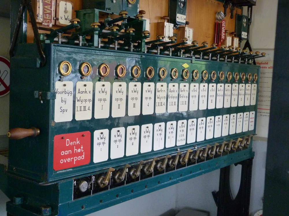
Command frame, post T, Simpelveld, 16.8.2015
On the left side, one can see an unexpected block instrument, namely the "Voorbijgang" instrument of a line block. The original operations manual for Simpelveld from 1960 does not show this instrument. What is it for – is there really another line block in place?
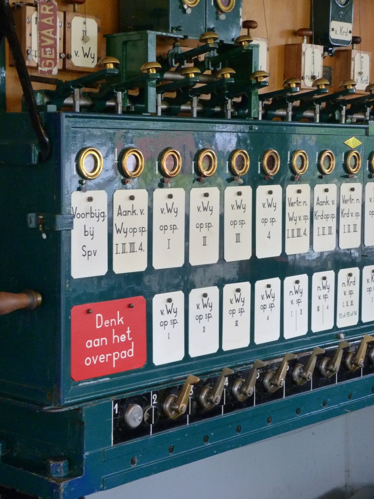
Command frame, post T, Simpelveld, 16.8.2015
The top of instrument shelf shows that this is actually the case: One can see two more instruments, marked "Enkelsp. Spv" and "Blok n.Spv". These instruments are operated by small levers that pull down a rod, in contrast to the standard instruments where the lever pushes the rod into the instrument. Obviously, such instruments cannot lock any signal or route levers, as they do not have rods going down all the way to the locking bed. But what is the purpose of these instruments? Unfortunately, I forgot to ask when I visited Simpelveld—but I would guess the following:
The signal box at Wijlre-Gulpen is usually not manned. Nevertheless, the line block between Simpelveld and Wijlre-Gulpen must be operated from Simpelveld's post II. The purpose of the three additional instruments at Simpelveld's traffic bureau is to "simulate" Wijlre-Gulpen in such a case, i.e., the train director handles the instruments as if he were at Wijlre-Gulpen. There is certainly a "one train on line" rule in effect, as it is not possible to reliably check that a train has fully arrived at Wijlre-Gulpen; and therefore, there is also no button lock for the "Voorbijgang" instrument:
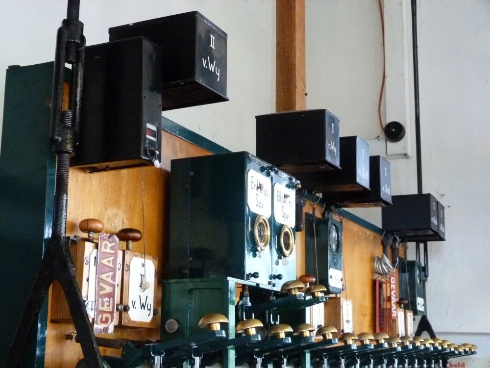
Bell and somewhat unexpected line block instruments on command frame, post T, Simpelveld, 16.8.2015
From post T, I walked towards post I. On the way, I took some pictures of signals and points. Here is a track plan so that you can locate the various items (click opens a readable PDF file):

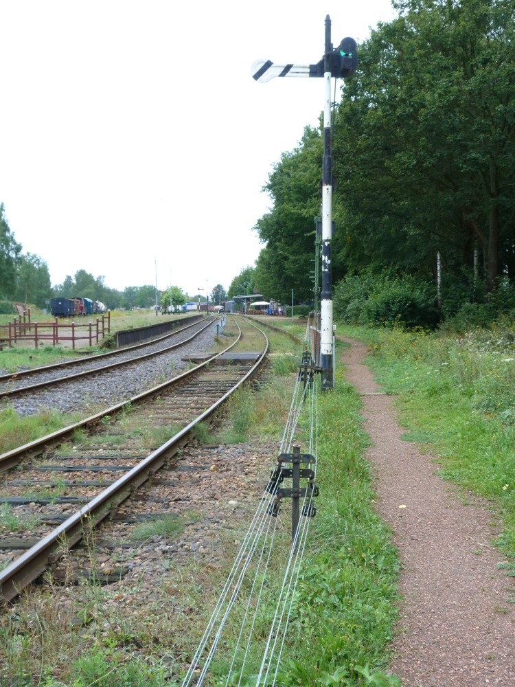
The next picture shows the starting signals towards Kerkrade and Bocholtz (the former line to Germany). In earlier times, there was a bracket with two arms at track 3 instead of the current single arm signal CKR3 ("signal C to Kerkrade or Richterich from track 3"). This signal is still cleared by two different levers, which requires some sort of "or logic" – this will be shown in a later posting. Signal C1 is located to the left of its track; a small plaque with an arrow indicates the track guarded by it:
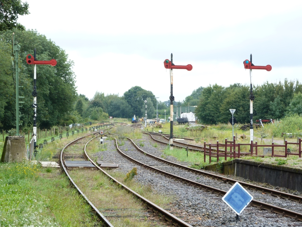
Starting signals C1, C2, and CKR3, Simpelveld, 16.8.2015
On the reverse side of the arm, one can see the typical diagonal stripes:
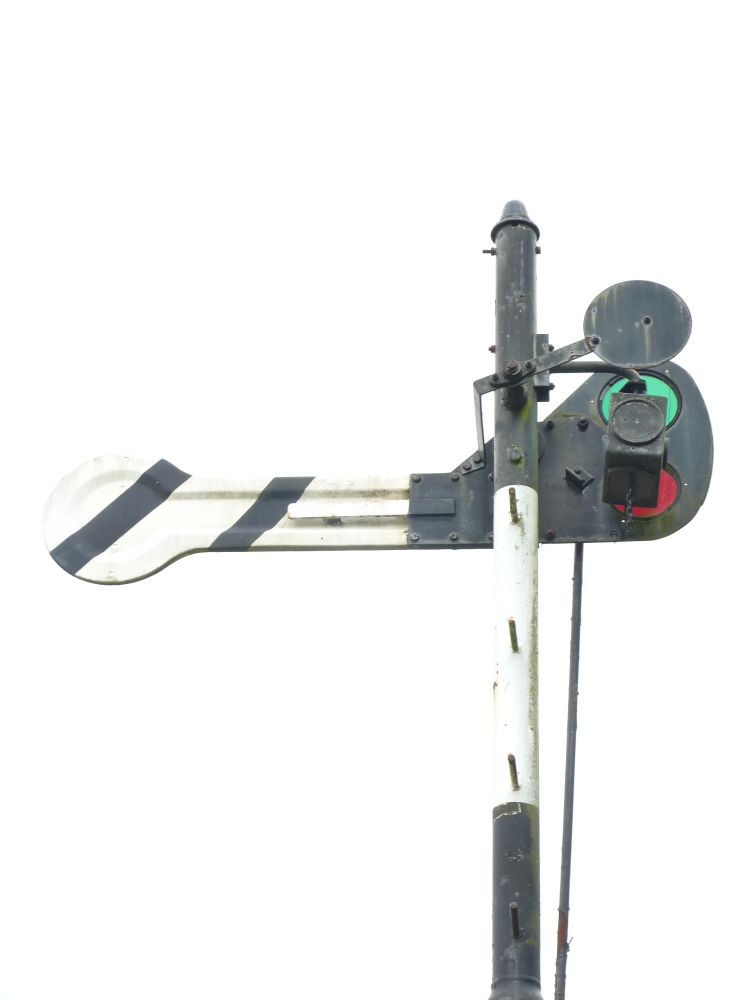
Starting signal C1, Simpelveld, 16.8.2015
Starting signal C1, Simpelveld, 16.8.2015
Between tracks 1 and 2, there is a small shunting signal. The two crossing arrows indicate that this signal governs both track 1 and 2. As shunting signals can be cleared independently of how the points lie, it is easy to have such "general purpose" shunting signals. Of course, drivers of two engines in track 1 and 2 must take care if this signal changes to clear so that they do not both start towards points 14:
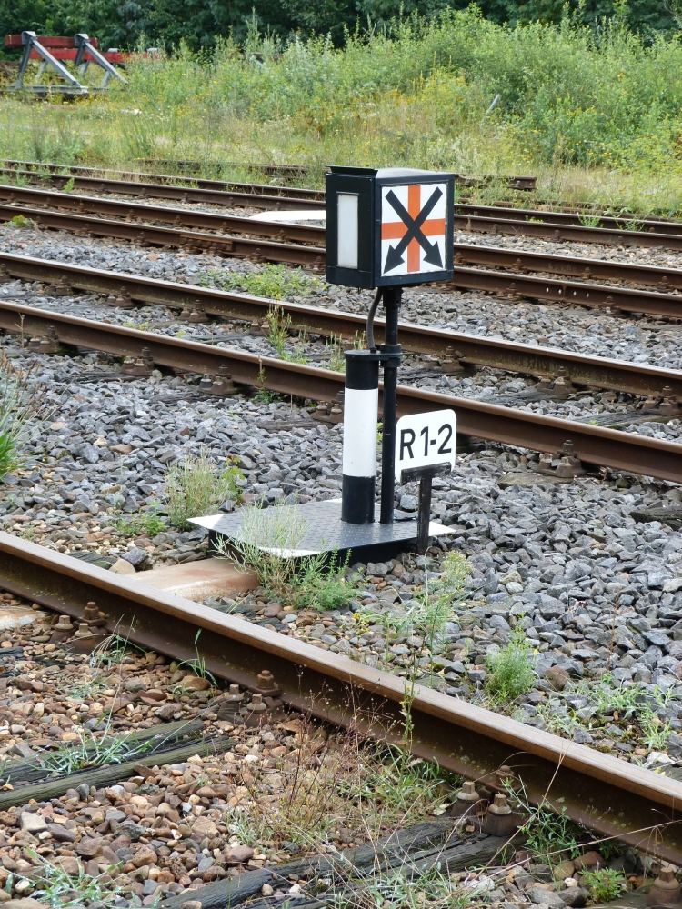
Shunting signal R1-2, Simpelveld, 16.8.2015
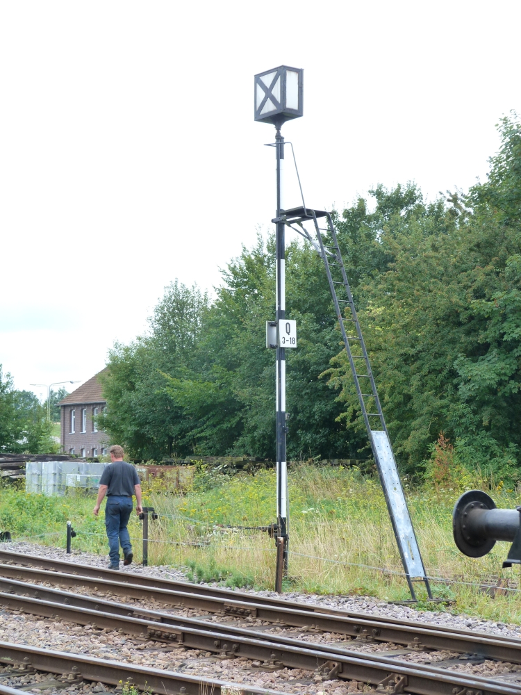
The high shunting signal Q3-18 governs movements on all the tracks from 3 to 18—i.e., all station tracks except 1 and 2 as well as the tracks at the engine facilities:
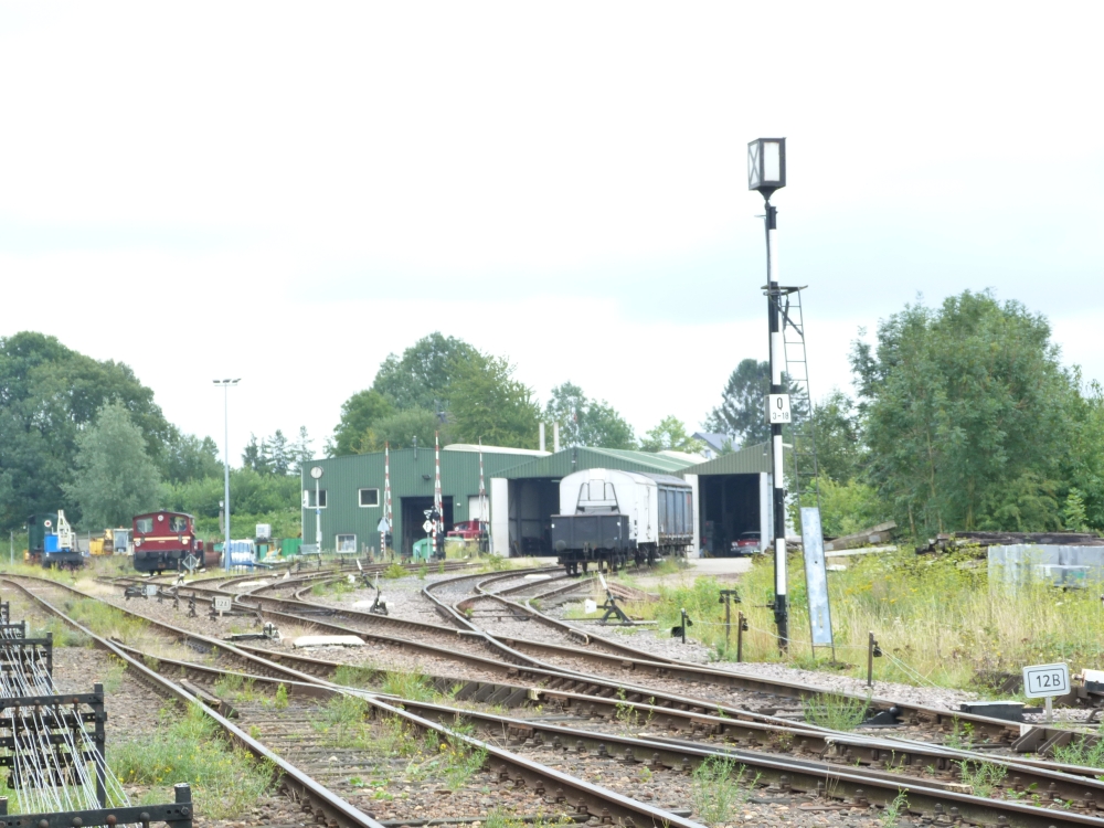
Shunting signal Q3-18, Simpelveld, 16.8.2015
The linkage for moving the signal consists of a simple open wheel, which is moved by the wires by about 180°. A crank moves the signal's head by about 90° in such a movement. This simple mechanism ensures that the position of the signal head is almost independent of a possible slack or lengthening in the wires—at both final positions, the rod to the crank is almost at the dead center of the movement:
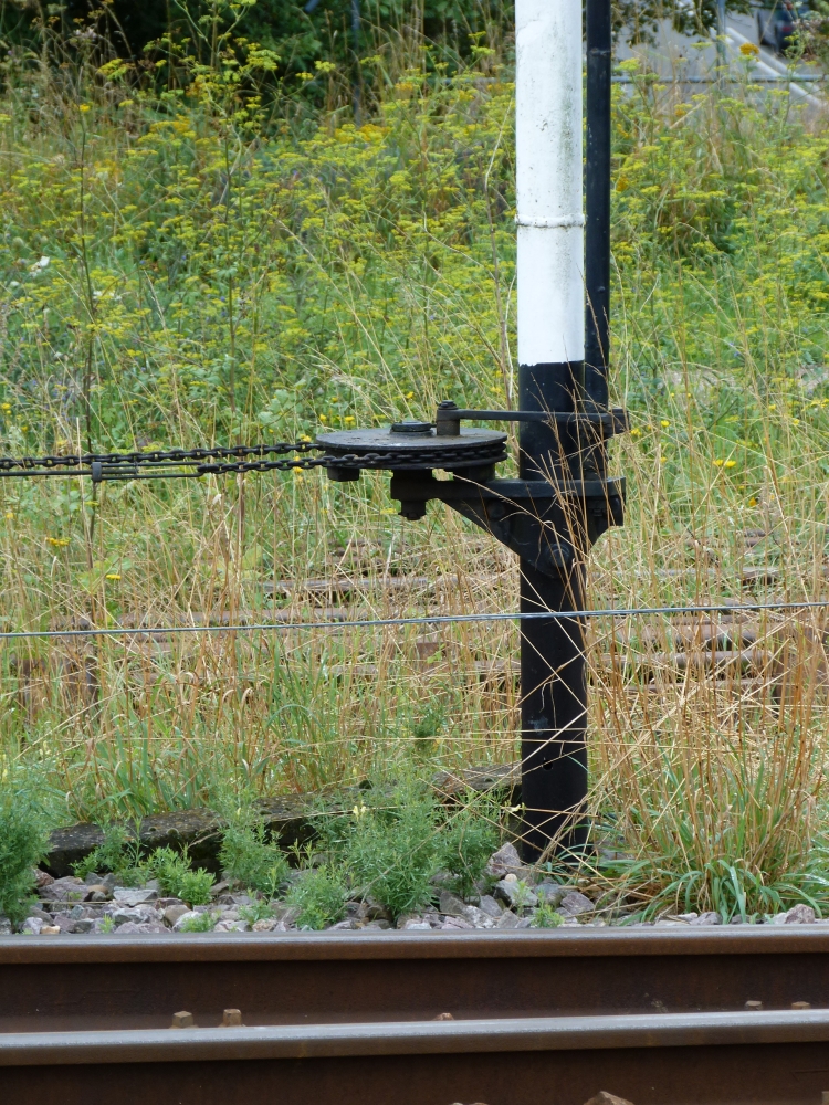
Shunting signal Q3-18, Simpelveld, 16.8.2015
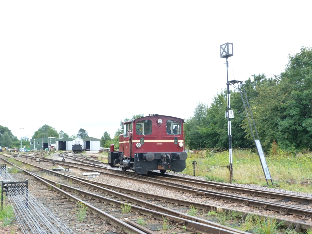
The small shunting engine 332-3 makes a run:
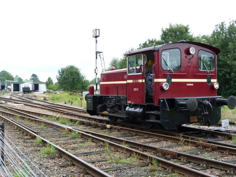
Shunting engine 332-3 in front of shunting signal Q3-18, Simpelveld, 16.8.2015
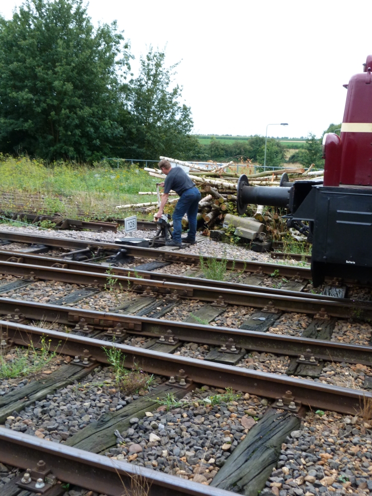
Reversing manually operated points 12B, Simpelveld, 16.8.2015
Shunting signal Q3-18, Simpelveld, 16.8.2015
Shunting engine 332-3 am shunting signal Q3-18, Simpelveld, 16.8.2015
Here are a few interesting pictures of points drives and locks:
Points 12A are operated from the ground, but they do have a facing point lock operated from the signal box. As mechanically operated points in the Netherlands do not have blade locks, they have to be locked explicitly for a train run:
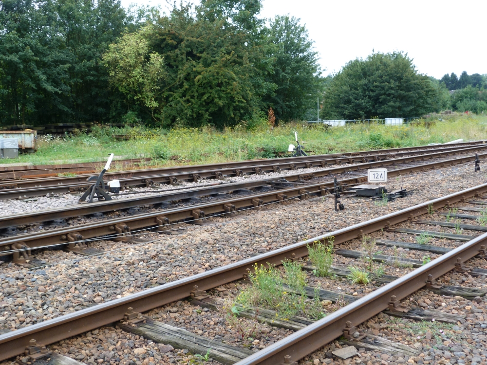
Points 12A, Simpelveld, 16.8.2015
The number 12A implies that there must be another set of points 12B which is worked together with 12A. The ground operation is separate, but they are both locked by the same lever in the signal box which means that there must be a single wire loop going through both lock mechanisms. The following pictures shows that actually, the wire coming from the signal box is leaving in another direction so that it can reach points 12B, from where the wire will return to the signal box:
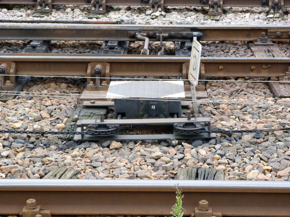
Lock drive at points 12A, Simpelveld, 16.8.2015
Even more interesting are points 13A—again, the number means that another set of points 13B is operated in tandem with this one. However, at 13A, train routes are possible over both branching tracks (see track plan above), so that it must not only be locked, but also be reversed together with 13B. The picture actually shows that for that mechanical points drive, the wire again continues to the other drive at 13B. In Great Britain, where points are moved not by wires, but by rods, it is very common that two opposing sets of points are reversed by the same lever. However, with double-wire installations, I have never seen this—with one exception: On the narrow-track Ybbstalbahn in Austria, a few pairs of points were also reversed by a single lever, e.g. at Göstling a.d.Ybbs. However, in the Netherlands, this connection of pairs of points was widely used: On klassiekebeveiliging.com, there is a number of track plans and signal box diagrams with such situations, some of them with Siemens&Halske type 3414 frames, for example Lunetten or Nieuwe Schans:
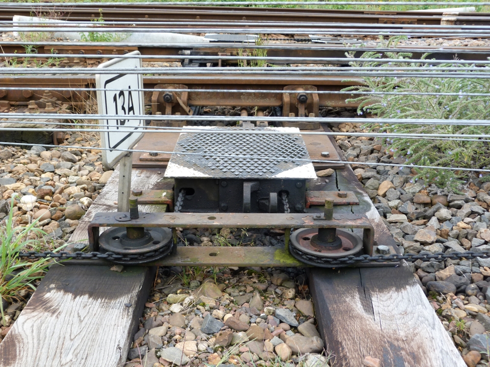
Points drive an der points 13A, Simpelveld, 16.8.2015
Last, but not least here are points 14 with their indicator.
Points indicators that make clearly visible whether the points lie to the left or to the right were apparently almost completely absent in the Netherlands, also from points moved by mechanical interlockings. On klassiekebeveiliging.com one can see a number of pictures, for example at Vork and Elst, where, like in Britain, points indicators are missing. This is interesting because Dutch interlockings rarely had shunting signals, and moreover these were not interlocked with points—in contrast to Britain, where tappet locking and similar locking technologies, with the locking bed always active, allowed the addition of shunting signals much more easily than the continental locking beds that acted only for train runs, but not for shunting. In Germany and Austria, the person responsible for a shunting move is on the ground near or on the shunted cars—but to make sure that shunting can proceed safely, he must be able to see which way points are set: This is the main reason for points indicators. How was shunting done safely in the Netherlands in stations where both shunting signals and points indicators were missing?
Be that as it may: Nowadays, such indicators seem to be required, and they are designed after the more modern fashion showing "left" or "right", instead of "lying straight" or "turnout":
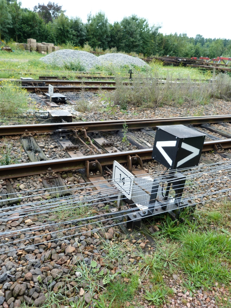
Points indiactor at points 14, Simpelveld, 16.8.2015
Here is the facing point lock of points 14. There are, obviously, two rollers inside, one above and one below the locking rods (which means that my assumption in the posting about Wijlre-Gulpen that the top cuts in the rods are from some previous use is most probably wrong: When the other track at Wijlre-Gulpen is also used for train runs, it must be possible to also lock the points in the opposite position—by another wheel on top which meshes into those cuts!):
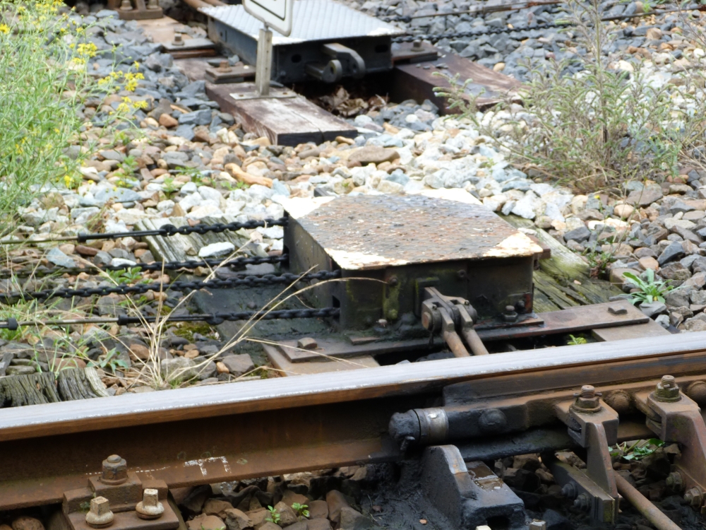
Facing point lock at points 14, Simpelveld, 16.8.2015
Finally, here are some double wire lines and connectors:
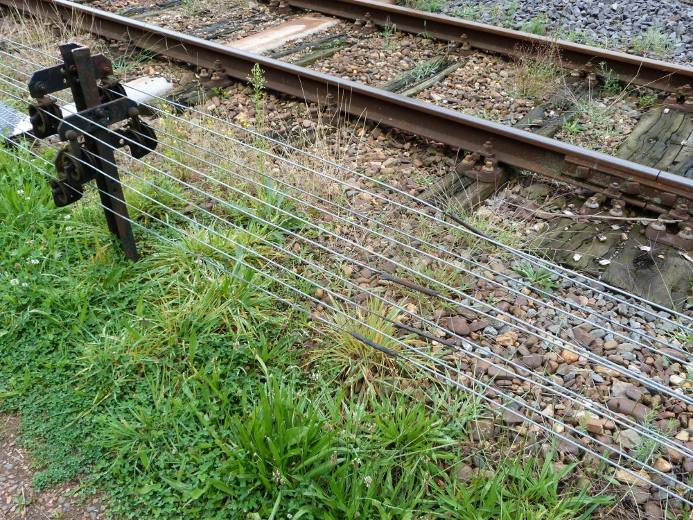
Wires, Simpelveld, 16.8.2015
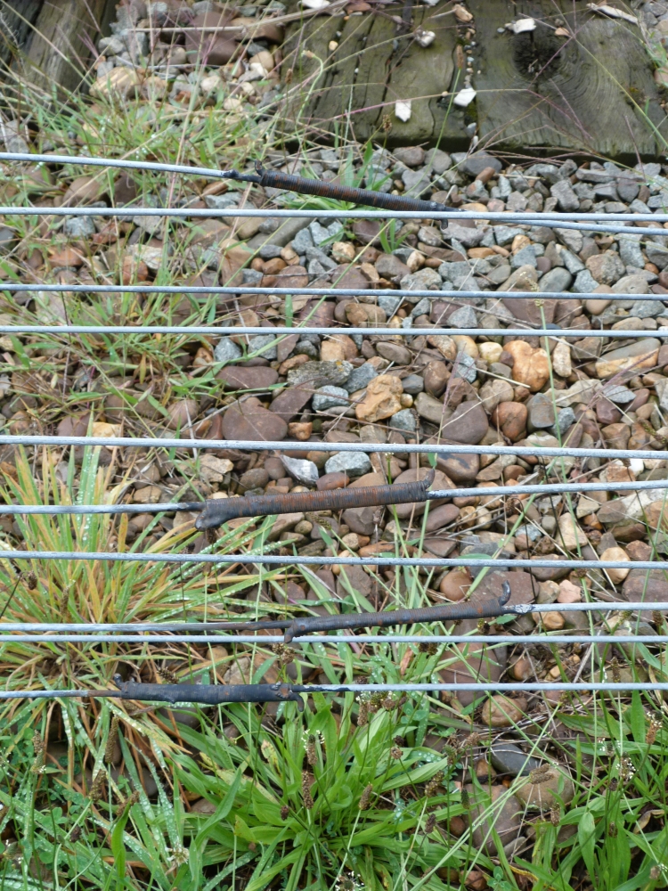
Connectors, Simpelveld, 16.8.2015
And here, we are approaching post I ...
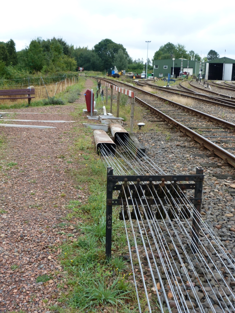
Double wire lines in front of post I, Simpelveld, 16.8.2015
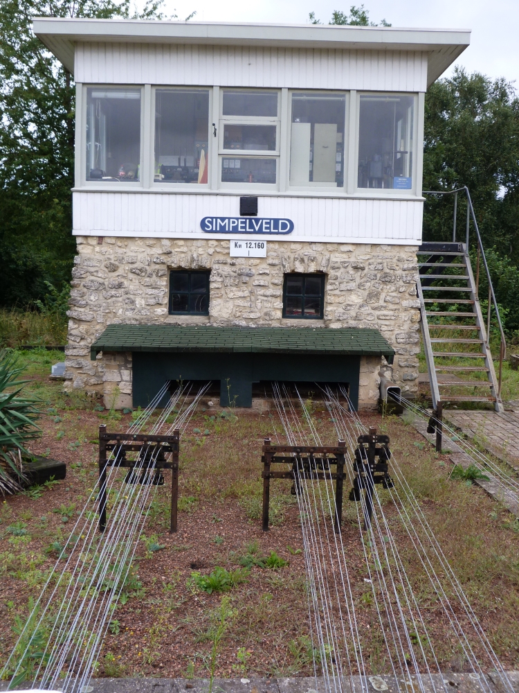
Post I, Simpelveld, 16.8.2015
... pictures of which I will show in my next posting!