This posting is an attempt to explain a piece of railway technology from Central Europe to all who are not fluent in German. Specifically, it deals with the functions of the "station block," which connects the traffic bureau and the signal boxes, on Austria's railways. In contrast to other explanations e.g. in books, I want to use the possibilities of the Internet in these explanations, namely animations and a few short videos.
Explaining railway technology is difficult because the railway is a system where many parts interact closely: Signalling technology for block working with technology at stations, line-side technology with train equipment, and—sometimes more importantly than devices alone—technology with rules and regulations and even concepts like "station" or "line." Therefore, it is almost impossible to explain a piece of railway working separately from its environment. Fortunately, there is a piece of writing that already explains much of this context, namely Jörn Pachl's splendid article "German Block and Interlocking Principles – An Introduction for the Anglo-Saxon Reader." And despite its title, almost all of it is also applicable to Austrian railways.
While quite a lot more could be said about the differences between "Anglo-Saxon" and "German" signalling and operating principles, I will delve head-on into the description of the interlockings of a typical Austrian station. I hope that many direct questions ("how does it work?") are answered by this text. On the other hand, many background question ("but why was it designed like that?") will go unanswered—and whereas I will try to answer some of them in a later posting, I fear that much of that is beyond my knowledge; or might even have to be answered with "because it was customary to do it like this" or the like. See also my short text on "Different ideas on technical risks" for that.
The large difference between German-influenced and English operation and interlocking practices is the result of two inventions:
- First, the invention of the Siemens block instrument by Carl Frischen in 1871, a device unknown in British and American interlocking technology. This device allowed a technically secure collaboration of persons working at different signal boxes and traffic bureaus. In contrast to English and American practices, this soon lead to (or rather set in stone) a hierarchical organisation of operational responsibilities over the area of each station, even if two, four or more signal boxes were necessary (in contrast to England, where each signal box's signalman is fully responsible for all train moves on the tracks assigned to that signal box).
- Second, the introduction of route locking by route bars by Büssing in 1875 (after a first use in a command frame by Siemens in 1872), i.e., all points for a route from a signal to the next signal (or the end of the rotue) are locked with a single interlocking movement. This is only viable because shunting movements are not signalled, hence it is necessary to lock points only for train routes.
At times, this lead to interesting situations: At the large hump yard at Wels, there was a signal box which counted as a junction for some movements, but as part of a station for others; therefore, some of its signals routes needed orders from one of the station's traffic directors, whereas other routes could be set up under the discretion of the signalman at the signal box.At this point, I need an English word for the persons working in signal boxes. But ... isn't it simply "signalman"? After thinking about this for some time, and after reading two very enlightening papers by Jörn Pachl that compare German, English, and American operational practices (which are, to my knowledege, unfortunately only available in German), I have decided that it is inadequate to translate one of the two important roles of "Fahrdienstleiter" and "Stellwerkswärter" as "signalman:" Whereas a signalman has roughly the responsibilites of "Fahrdienstleiter", the word "...leiter"=leader implies that there are typically (two to many) people that are lead, i.e., subsidiary to the "Fahrdienstleiter"—which is not a connotation of "signalman." Hence, I use the term "traffic director" for "Fahrdienstleiter" and the word "pointsman" for "Stellwerkswärter" (even though a "Weichenwärter," which is the direct translation of "pointsman," is another role with typically less responsibilities than a "Stellwerkswärter"—but I skip these fine points), and circumvent the term "signalman" altogether. So if someone asks, after reading my texts, "But where is the signalman?," the answer is "the combination of the traffic director's decision-making responsibilities and the pointsmen's manual work is equivalent to the signalmen." In rare cases, however, the term "signalman" seems appropriate—e.g., in the special situation at Wels described above.
A few more notes on command frames: Historically, there have been instances of connecting command frames with lever frames by mechanical (instead of electrical) means. One example that survived into the 1980s and which is now a heritage signal box is located at Kerzers in Switzerland. Moreover, there were stations where the traffic bureau was located near one throat of the station, which sometimes (but not always!) lead to the integration of this throat's lever frame with the command frame for the signal box at the other throat. In such a case, the "Fahrdienstleiter" would have both roles and could properly be called a "signalman." Examples of such setups were Oberdrauburg in Carinthia or Bad Ischl Frachtenbahnhof (goods yard)—at the latter one, the type-5007 frames are still in use up to now!
In Germany, the combination of command frame and one side's lever frame was the rule (rather than the exception, as in Austria), and hence the traffic director is almost always located in one of the signal boxes, whose abbreviation is then, customarily, followed by an "f"—e.g. Wf for "Walheim Fahrdienstleiter(stellwerk)". This would, in turn, require an additional employee at the station building proper for selling tickets and handling goods contracts—a role that in Austria was, at least in smaller stations, traditionally filled by the centrally placed Fahrdienstleiter.
In our modern times, where operational and commercial responsibilities have been completely separated at each station, this lead to locked traffic offices everywhere—however, older people in Austria still knock on the Fahrdienstleiter's door to ask him everything from timetables (ok) to train delays (mostly ok) to ticket prices (not ok) to policies for returning unused tickets (not at all ok), only to get told that he no longer can answer that. In Germany, where the operational and commercial responsibilities had been separated in many more stations, this change was not felt so sharply as in Austria (the exception being many German stations with a single lever frame in the middle). So much for that.
But now let me finally start with the explanation of station block working!
This and a following posting show the interaction of the command frame and the lever frames from the viewpoint of its users, viz. the traffic director and the pointsmen. The exact mechanical details of the interlocking and the necessary electric circuits are not part of my explanation. However, I will nevertheless present animations of an "inside view" of the frames involved—this should help to understand the dependencies between the various parts much better. Yet, I'll present a very simplified version of these inner parts, because their actual construction would again require many more explanations.
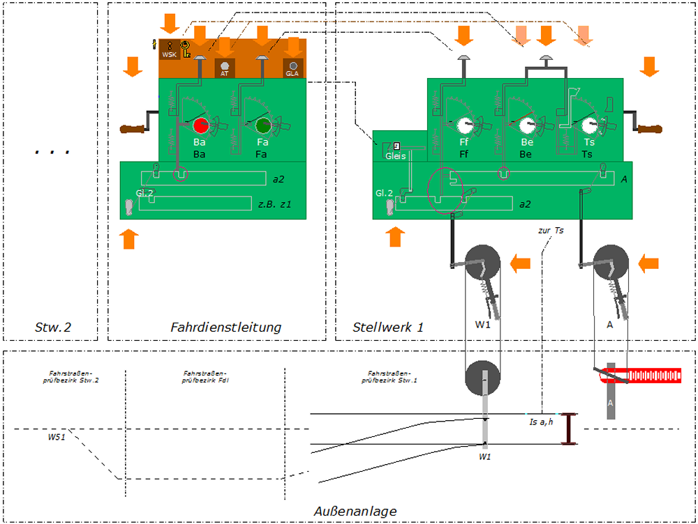
As a teaser, here is a drawing of all the mechanics that will come to live in the animations (I did not change the German texts in the animations—I think the operation can nevertheless be understood from the diagrams and my texts):
This is my first attempt at such larger animations. Even though I have worked on them for almost two months, I am not yet satisfied with them. E.g., the "camera work" is quite static—that could be better! I am therefore happy about any comment, hints or ideas about improvements
My explanations are based on the traditional frame setup at an Austrian station:
- The traffic bureau is located in the central station building. The traffic director uses a "command frame" in the traffic bureau to dispatch "commands" (routes to be set up) to the signal boxes.
- At each station throat, there is a separate signal box ("throat box"; "Endstellwerk") controlling the points (and FPLs) as well as the home and starting signals in its "half" of the station tracks. In each signal box, a lever frame controls the points, FPL, and signal levers. Electric locks on top of the lever frame provide the necessary interlocking between the command frame and the levers at the signal box.
In the following, I will explain a train movement at a signal box about four times, starting with a short overview and ending with detailed animations. I will skip most details related to rules and regulations, mainly because this would make the explanations even longer, and second because.
1. Short description of a train movement
When a train runs through a station (with or without stopping there), the following happens:
- About three to five minutes before the train is due, the traffic director selects both a route for entry into and one for exit out of the station on his "command frame" and then transmits the corresponding orders via block instruments to the signal boxes. By pushing a button, he also informs them about the (line and running) tracks to be used for the movement.
- Each of the pointsmen now sets his points and FPLs and locks them mechanically and electrically, which allows him to clear the corresponding signals. The mechanical interlocking between points and FPLs levers one the one hand and signal levers on the other hand enforces the legally required dependencies between points and signals.
- When the train traverses the route, it releases the "button lock" at the lever frame.
- Each pointsman checks the train's tail lamp and then returns the signal(s) to their stop position. Then he "blocks back the order" to the command frame via a block instrument.
- The traffic director blocks, for each ordered route, another block instrument, which releases the electric route lock at the signal box.
- Both the traffic director and the pointsmen can now reverse their route levers. At the signal boxes, the points levers are now no longer locked, and hence the points can be used for shunting or other train moves.
2. Functional groups
The following images show the parts of the frames that are necessary for setting up routes.
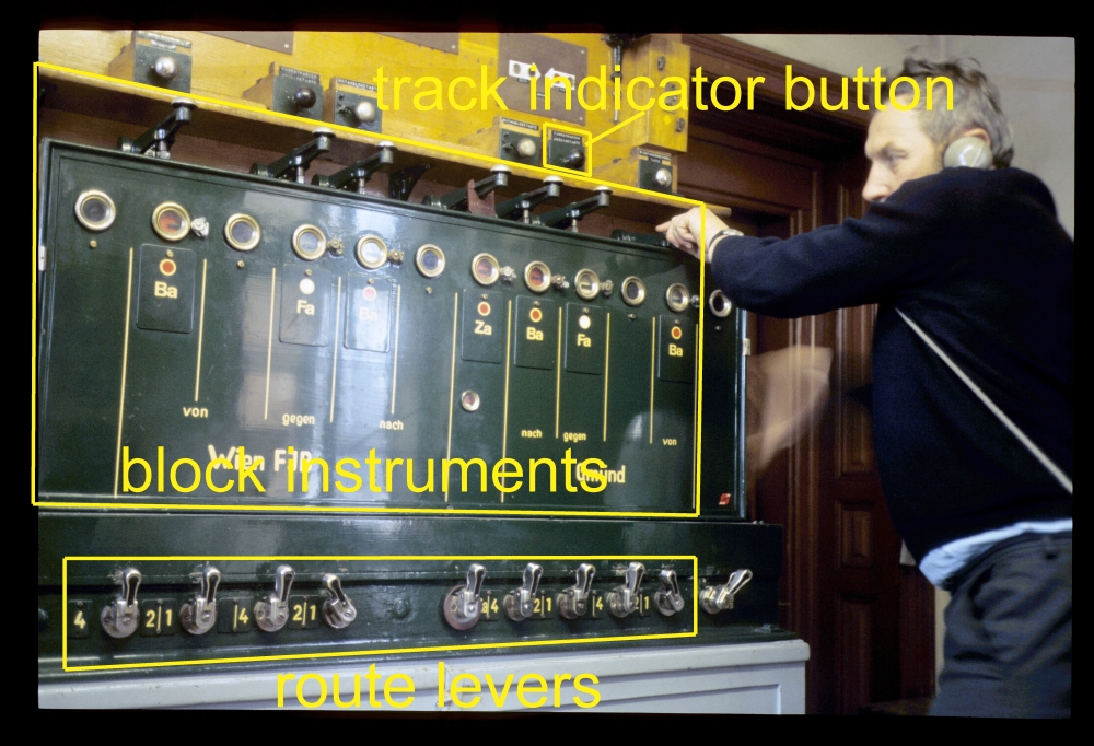
The command frame in the traffic bureau contains devices for three purposes:
- Small route levers select the running tracks to be used (step 1 above).
- Block instruments transmit the orders (step 1) and release the routes at the signal box later (step 5).
- A track indicator button triggers the track indicator at the signal box (step 1).
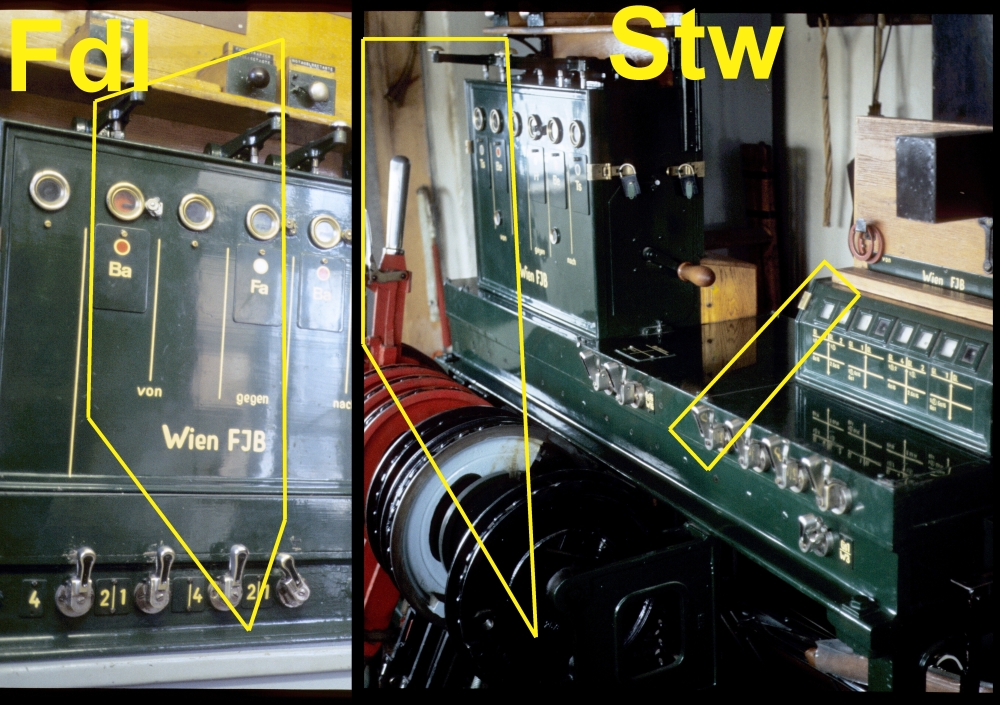
The following picture shows a traffic director transmitting an order (step 1) to signal box no.1 at Ziersdorf. The abbreviations on the block instruments are as follows:
- Ba = Befehlsabgabe; literally "command dispatch"
- Fa = Fahrstraßenauflösung; literally "route release"
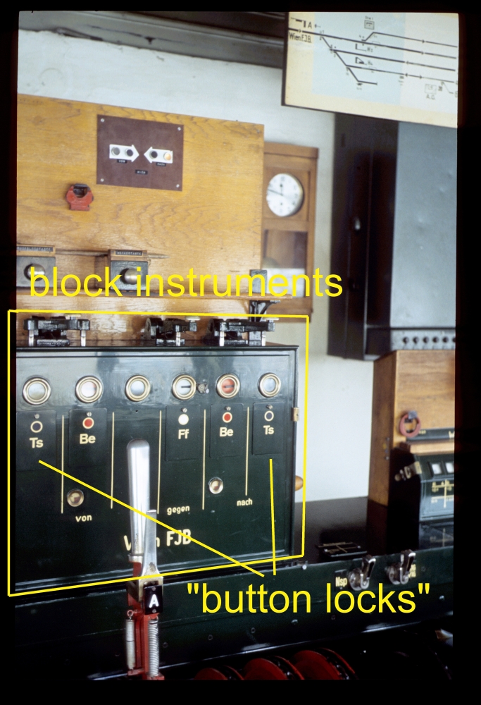
At the signal box, four purposes are served:
- The block instruments receive and return orders (steps 1 and 4) and lock routes electrically (step 2).
- The track indicator shows which running track is to be used (step 1).
- Route levers lock routes—i.e., all levers needed by a route—mechanically (step 2).
- Finally, the lever frame holds the points and signal levers (step 2).
The next two pictures show these devices at the signal box no.1 of Ziersdorf. The abbreviations on the block instruments are:
- Be = Befehlsempfang; literally "command receive"
- Ff = Fahrstraßenfestlegung; literally "route lock";
- Ts = Tastensperre; literally "button lock";
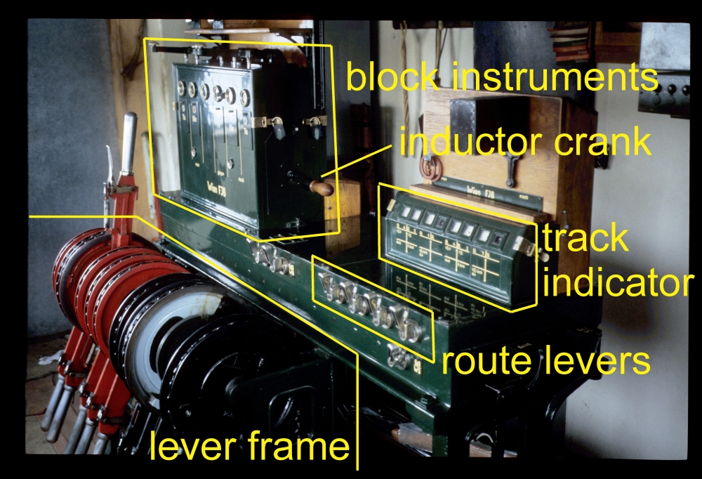
Ziersdorf was a real, albeit small station with three running tracks. However, for my explanations I will reduce the complexity even more to the bare minimum: I will look at one signal box, one direction of travel and one running track—in effect, one single route. Thus, I "cut" the following parts from Ziersdorf's frames (the two abbreviations mean: "Fdl"="Fahrdienstleitung"="traffic bureau" and "Stw"="Stellwerk"="signal box"):
I will place this single route in a station that
- has only one set of points on each side of the station,
- does not need FPLs (presumably, the maximum speed on the line is only 40kph),
- has only single-arm semaphores (which is allowed on such a slow line)
- and still has "throat boxes," i.e., a signal box at each end of the running tracks.
But before I present the working of 5007 frames in animated detail, let me describe with one more piece of text, namely a "sequence table."
3. Sequence table of a train movement
The following table describes the standard procedure for a train movement past a signal box equipped with a type-5007 frame, together with the necessary actions on the command frame in the traffic bureau. The table shows, in each column, the state of a part of the system—in this case, block instruments and levers. Each state change is marked by a bold black line that is accompanied by the state descriptions. For block instruments, these short descriptions are shown in the respective colour shown in the block instrument's window. On the left, there is a "narrative" of who does what during the train movement. A click on the table opens a more readable PDF file:

Of course, there are many more operation sequences in the case of technical or operational problems. For example, it must be possible to revoke an order if the station in the rear needs to change the order of trains on short notice; or it must be possible to run trains as securely as possible even if a signal is out of order. This type of problems has a significant impact on the design details of the various parts involved—however, I'll ignore all this in the following description and proceed as if everything worked completely regularly.
4. Animations
The following six animations, finally, show the actions during a train movement as experienced by the traffic director and a pointsman. In these animations, green covers hide the inner details—in the next posting, I will then reveal what's going on "behind the scenes." Each animation has flashing orange arrows that point to the place where someone has to do something. My main modelling work went into the central and signal box frames, whereas I neglected the details of the points and the signal—for example, the points should have blade locks (when I have lots of time, I might add such details). The numbers besides the paragraph headings refer to the steps of the table in the previous section. The animations should be detailed enough to view them in full-screen mode—this might reveal one or two details that are hard to detect otherwise.
4.1. Traffic bureau: Transmit order (2,3)
In this first step, the traffic director selects a route and blocks the Ba block instrument. This unlocks the signal lever (therefore the block instrument was called "signal lock" in earlier times) and counts as an order to set up the route at the signal box. In the command frame, this route selection prevents the selection of other, conflicting routes.
A tap on the track indicator button, together with a turn of the inductor crank, drops a small sign in the signal box that shows the track to be used. However, this operation is not connected to the interlocking proper, and it can be (and is) omitted if the train will use the track indicated in the schedule.
The following short video shows this sequence in the traffic bureau of Sigmundsherberg, ...
... and here we see how the Be block instrument at the signal box is unblocked:
(Unfortunately, these videos are without sound, so you miss the characteristic rattling of the block instruments; but there will be a video with sound in the next posting).
4.2. Signal box: Set up route and clear signal (4,5,6,7)
The pointsman sets the points and, where needed, their FPLs for the required route. As the points have to be in their normal position when not used otherwise, this often means that only a few FPL levers have to be reversed. In my example, however, the train should go into track 2, and therefore points W1 have to be reversed. One can see that the rod leading into the locking bed is moved by the catch handle, but not by the lever itself: When the catch handle is pulled, the rod moves the first half of its travel; it remains stationary during the reversal of the lever, and moves the second half when the catch handle is released.
After all levers have the required position, the route is mechanically locked by tilting the small route lever. The route bar in the locking bed now prevents any movement of the rod leading to the lever and therefore locks the catch handle, which in turn locks the lever in place.
By now blocking the Ff block instrument, the pointsman locks the route bar electrically. From this point on, he cannot (except by emergency measures) unlock any lever without a release action of the traffic director. But on the other hand, the blocked Ff instrument now releases the signal lever, so that, finally, the pointsman can clear the signal.
Here are two short videos that show the blocking and unblocking sequences: At the signal box, the Ff block instrument is blocked ...
..., in the traffic bureau we see the sequence from above, extended by the unblocking of the Fa block instrument (the signal man must have stood near the instrument so that he could block his Ff instrument right after the order was transmitted):
4.3. Train passes by (8)
Instead of returning the order (by blocking the Be instrument) after the train has passed, an eager pointsman might do this too early. A careless traffic director might then release the route, and the pointsman could then reverse points right in front of or under the train. Of course, this must be avoided, and therefore, the train itself takes part in the release sequence: By shortcutting a short insulated piece of rail, a relay is energised which in turn unblocks the "button lock" block instrument. Only when this has happened, can the pointsman block the Be instrument.
However, the animation shows two problems with this design:
- The button lock is released by the first axle of the train! It seems that the Be instrument could be unblocked at a very early point of time, while a long train is still rattling over the points. This problem is solved by putting a contact of the relay mentioned above in the Be circuit, so that blocking of the Be instrument is prevented while that relay is energised. This remains so as long as train axles move over the insulated rail.
- When a train enters the station, its wheels pass the insulated rail before negotiating the points! Therefore there is, at least with a slow train, still the possibility that the pointsman blocks back the Be instrument after the train's last axle has left the insulated rail, but still rumbles over the points. If blocking the Be instrument released the route directly, the pointsman could then immediately reverse points under the train! This possibility was the original reason that the traffic director is involved in the route release process at all: One hopes that two people together might not make that mistake in the limited time when the rear end of the train traverses the points—especially when one of them is responsible for all train movements in the station area. Still, from the 1930s onwards, for entry into a station, separate insulated rails were put inside each running track, so that a train entering the station would unblock the button lock only after it had passed all points with all axles. The participation of the traffic director in the release sequence was nevertheless kept also after this enhancement. By the way, the insulated rails in each track lead to the introduction of two different markers for fouling points in Austria: The "small marker," two red-and-white knobs, marked the actual "geometric" fouling point where the tracks after a turnout had the minimum clearing distance; the "large marker," the common black-and-white bar, marked the end of the insulated rail, i.e., the point to which a train's rear end must advance so that the button lock is unblocked.
4.4. Signal box: Return signal to stop (9,10)
When the train passes the signal box, the pointsman checks the tail lamp. Only after that, he may return the signal to the stop position. This now allows him to "return the order" by blocking the Be instrument. The points levers, however, are still locked by route bar that is in turned locked by the Ff instrument. Together with blocking the Be instrument, by mechanical linkage, also the button lock (Ts instrument) is blocked into its locking position. Thus, the next train movement will require a new transmitted order (unlocked Be instrument) from the traffic director.
4.5. Traffic bureau: Release route (11,12)
The route release proper is done by the traffic director: He blocks the Fa instrument, which unlocks the Ff instrument at the signal box and hence releases the route bar at the signal box.
4.6. Signal box: Move points to normal (13)
The unblocked Ff block instrument makes it now possible for the pointsman to return the small route lever to its vertical position. This, finally, releases the mechanical lock on all the locked levers (or rather their catch handles) so that FPLs can be returned to their normal, unlocked position; and points and shunt signal can be set as needed for shunting or other train movements.
So much for the first three explanations—a short one, a table, and a sequence of animations—of the co-operation of a traffic director and a pointsman (or, rather, a command frame and a frame at a signal box) under Austrian station block working.
In the next posting, I want to present animations of the inner workings. They will be of quite simplified versions of all the instruments, but still should allow to understand part of what happens behind these green covers!
This description and animation is really interesting and informative, but the omission of the signalbox at the exit of the simplified station leads to some confusion. How is the signaller at the entry box prevented from clearing the entry signal if the signaller at the exit box hasn't confirmed the route? Do both signal boxes have route levers for all routes that lead into or out of their district? What actions does the signaller at the exit box have to do in order to set and lock a route?
ReplyDeleteCould you write a follow-up post describing how two trains would cross at a station on a single-track line?