Showing posts with label My 12SA frame. Show all posts

Monday, April 28, 2014

Test runs with the 12SA and 5007 lever frames at Grafenberg, 2014

Deutsche Version dieses Postings

My friend Werner has completed much of the work at his "Sammlung Grafenberg", so in the week before Easter, we did a few first test runs—which was quite much fun! Here are a few photos and videos from this meeting.

Werner has
  • completed "Steyrling" (which was the original station controlled by my 12SA lever frame),
  • hooked up the semaphore and two sets of points
  • and connected the telephones between the original "Absdorf" station and "Steyrling" ...
... and with that, we were up and running.

Not everything was working flawlessly at that time—the semaphore's lower arm was somewhat too low, the tracks were a little wobbly, and the telephone batteries had been depleted through the winter, and/or some contacts were a little corroded.

Since then, all that and more has been fixed:
  • There are now double on each side of the wagons and locos,
  • the locos have magnets to simulate track circuits,
  • the tracks have been screwed down at most places,
  • the semaphore's lower arm has been weighted,
  • and all the points at "Steyrling" have been hooked up to the frame.

Here are a few videos and photos from the "inauguration meeting"—where I discovered that my knowledge about Austrian train handling procedures has gotten quite rusty over the last 30 years. Thus, we skipped some of the necessary offer-and-accept procedures for single-line working (we convinced ourselves that the model railway's DC supply was a sufficient safety measure against collisions ;-) ).

Here is the 12SA frame, now located in an old work hut from the NÖVÖG, which is now "Steyrling"'s signal box:
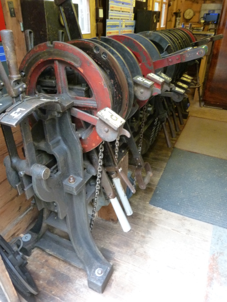
12SA frame "Steyrling", Sammlung Grafenberg, 16.4.2014

Some levers got original chains which move the contacts to control the model railway. These chains thus do not lead to any outside devices, but are "short-circuited":
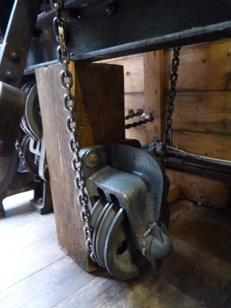
"Short-circuited" points chain, 12SA-frame "Steyrling", Sammlung Grafenberg, 16.4.2014

Here is a photo of one of the model railway's locos—more of them can be seen in some of the videos and on Werner's homepage:
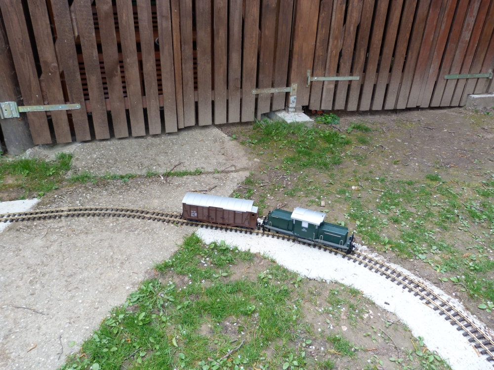
Model railway, Sammlung Grafenberg, 16.4.2014

This is a shot of the old home signal A of Hetzmannsdorf-Wullersdorf, which is now used as home signal D of "Steyrling":
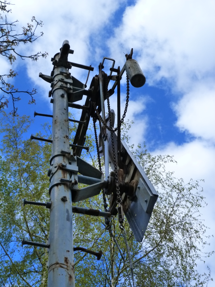
Home signal D of "Steyrling", Sammlung Grafenberg, 16.4.2014

After we met, Werner has also installed a model semaphore as starter C, which has also been hooked up (electrically) to the 12SA frame:
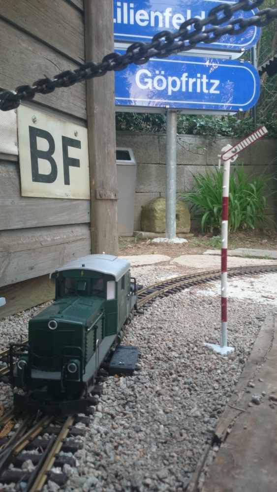
Starter C of "Steyrling", Sammlung Grafenberg, 23.4.2014

Besides "my" (but now Sammlung Grafenberg's) 12SA, one of the old lever frames that served at Absdorf-Hippersdorf has been moved to Grafenberg:
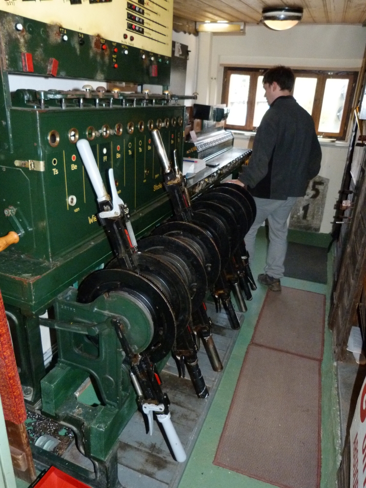
5007 frame "Absdorf", Sammlung Grafenberg, 16.4.2014
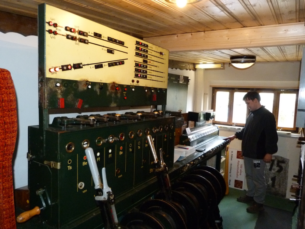
5007 frame "Absdorf", Sammlung Grafenberg, 16.4.2014
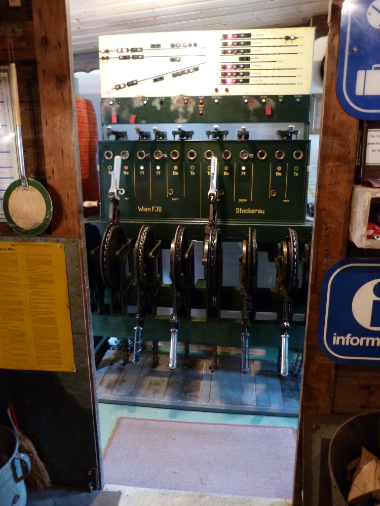
Frame and block instruments, 5007 frame "Absdorf", Sammlung Grafenberg, 16.4.2014
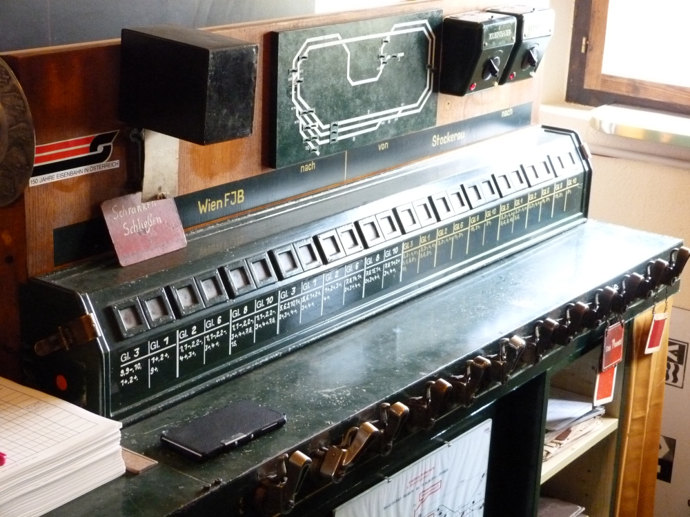
Track indiciator, 5007-Stellwerk "Absdorf", Sammlung Grafenberg, 16.4.2014

But now finally for a few impressions from our train runs. Here is my work place at "Steyrling":
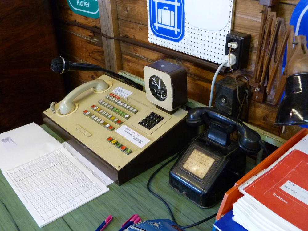
Traffic director's (signalman's) workplace at "Steyrling", Sammlung Grafenberg, 16.4.2014
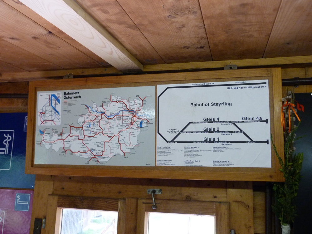
Track plan and instructions for handling of the 12SA frame at "Steyrling", Sammlung Grafenberg, 16.4.2014
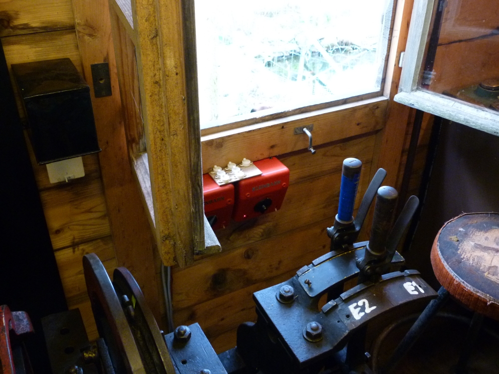
Model railway transformers and track switches for "Steyrling", Sammlung Grafenberg, 16.4.2014

And now for some action: The first train is announced:


Here it is:


A contact drops the warning bell, and then there's some work to do:


Actually, I was a little late, as can be seen here. It took me some time to get used to the controls of the various track supplies, and the track at that day still had a small kink with consequences:


Still, the signal must be returned:


A little later, I had announced my train to "Absdorf"—however, I had forgotten to turn the engine on the its side. Ok—more work:


But Werner used the time slot to send me a light engine which should fetch a wagon from the loading track at "Steyrling" (there's a photo of that train somewhere above):


The two metal bars that can be seen here are necessary to reduce the wire travel for the semaphore from the signal lever's 500mm to the signal's 250mm. We took the raw design of this device from the Slovenian Railways, where old Austrian "Drahtnachzughebel" (wire pulling levers like this one at Greifenburg-Weißensee; the weights only have a function when one of the wires breaks) had been replaced with the simpler version at some places (an example can be seen in this posting in an Austrian railway forum). Our design is simpler than the original one and also matches the heights of chains and wires for the signal better. Unfortunately, there was still that kink in the track ...


... but it has been since repaired, tells me Werner!

And here, finally, the two track lists we filled out during our "game of trains". At least, we managed to end up with the same number of entries :-) ... but as I said before, I'll have to work a little at my knowledge of procedures!
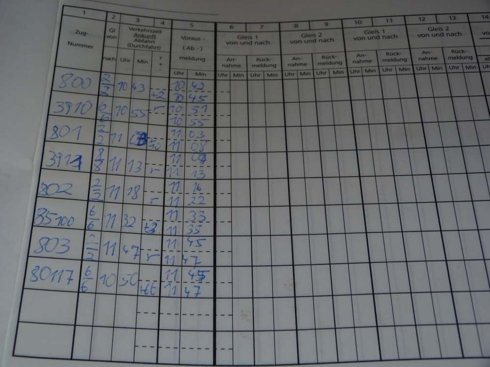
Train register "Absdorf" of our running day, Sammlung Grafenberg, 16.4.2014
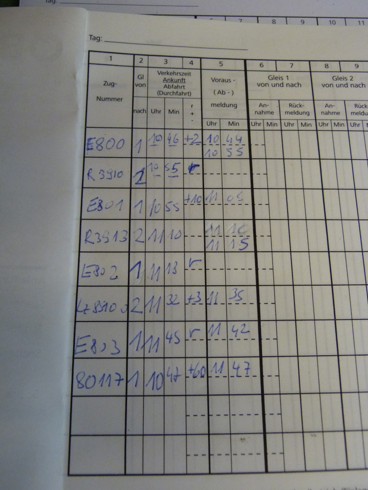
Train register "Steyrling" of our running day, Sammlung Grafenberg, 16.4.2014

Sunday, May 26, 2013

My Austrian type 12SA lever frame: Locking the distant signal

Here is the last lock type of the 12SA interlocking: The simple lock between a home signal and its distant signal.

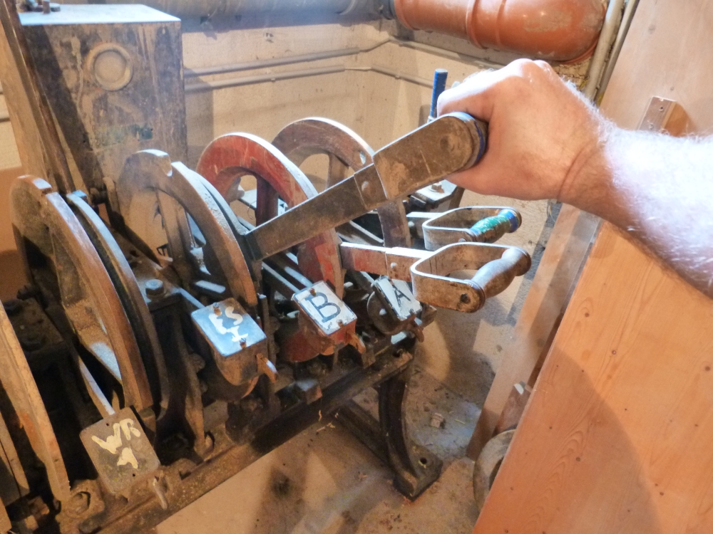
Of course, the distant signal had to remain in the "stop" position as long as the home signal was also not "clear." This rule was enforced by a simple bolt that moved into a hole either in the chain wheel of the home signal lever or of the distant signal lever. Here is a short video that shows how the home signal and then the distant signal is moved to "clear:"
  • First, the home signal lever is reversed.
  • Then, the small bolt is moved to the right with a small lever. Now, the home signal lever is locked, and the distant signal lever is free to move.
  • Finally, the lever of the distant signal is reversed.

Clearing home and distant signal

Here is a sequence of images showing the same operation:

Normal position

Clearing the home signal

Clearing the home signal

Clearing the home signal

Reversing lock lever

Clearing the distant signal

Clearing the distant signal

When the signals are returned to their normal "stop" and "stop expected" positions, the levers are moved the other way round:

Returning distant and home signal

On my 12SA, similar locks were also used between the fouling bar levers and the home signal levers. This was necessary so that the electric lock (described in the previous posting) would have to be engaged before the corresponding home signal could be cleared.

On small signal lever installations, this sort of lock was also used to prevent that the opposing home signals could be cleared at the same time. Here is an example from the small town of Horn in Lower Austria, where home signal A is "clear," while the lever of home signal Z is locked in the downward "stop" position:

Home signal levers, Horn, 20.9.1986

Saturday, May 18, 2013

My Austrian type 12SA lever frame: Electric locking of routes

After quite some time, here is a description of another part of my old Austrian 12SA lever frame.

12SA frames were mainly used on secondary lines, for example on the Murtalbahn, the Ybbstalbahn, but also around Ried im Innkreis. However, older installation were installed on main lines, like my 12SA, which stood in Steyrling on the Pyhrnbahn, south of Linz. For such cases, they were equipped with additional features not ordinarily used on secondary lines. One such feature, which I described in a previous posting, is the use of levers that survived running through points. In addition to that, my lever frame has the following two features:
  • Fouling bars ensured that no vehicle was going over points to be reversed. Due to frequent failures (especially in winter) and expensive maintenance, all such bars had been removed decades ago. However, the corresponding levers had survived on my frame because of ...
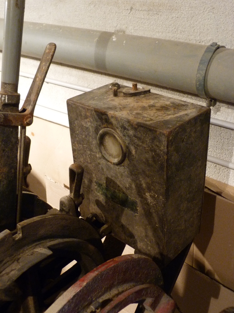
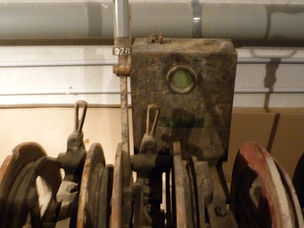
  • ... the second feature: Routes over facing points were electrically locked so that the points could not be reversed too quickly after a train had passed the home signals. The green boxes on the left and right of my frame contain mechanical devices for this purpose. And because these devices locked the fouling bar levers, which in turn locked the route bars (see this posting with the locking chart), the levers had not been removed—but now only served as an intermediate locking device on the frame.

Let us take a look at these electric locks.

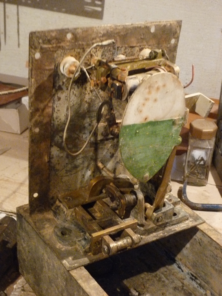
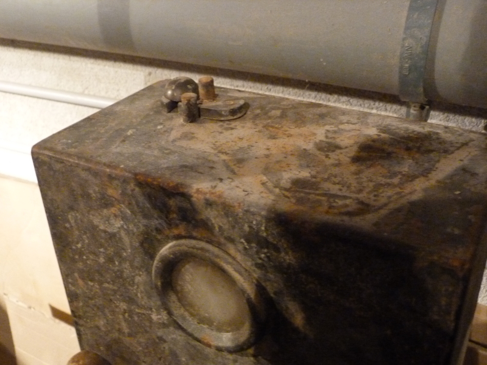
Here is the left box (still dirty from when it was submerged about ten years ago in the Danube and Kamp floods). Behind the glass pane, one can see a white sector which indicates that the fouling point lever is in normal position, and hence the route is not locked:

Electric lock in released position

The following picture shows the green sector behind the pane indicating a reversed fouling bar lever, which in turn locks the route bar in reversed position (however, unfortunately, I had removed the connection between the fouling bar lever and the electric lock before taking this picture, which is therefore somewhat misleading. When I find time, I'll replace this picture with a correct and focused one ...):

Electric lock in locking position

But now, let us look how the electric lock works. This picture shows the fouling bar lever in the middle. One can see that the locking weight lever is extended and ends with an upward part::

Locking weight of fouling bar lever

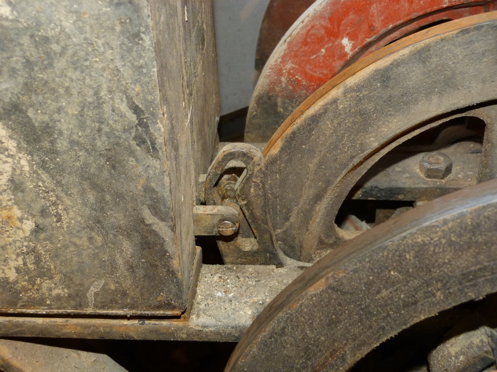
Here is the upward part again, which is crossed by a bolt on a bar vanishing in the electric lock:

Locking weight lever of fouling bar lever

Again the upward part, and one can see that two bars go into the electric lock. Both the fouling bar lever and its locking weight lever are in normal position here:

Locking weight lever of fouling bar lever

Now, I lift the locking weight lever (of the fouling bar lever), which is only possible if the route bar for an entry route has been reversed. Lifting the locking weight lever pushes the bolt a little bit towards the electric lock:

Locking weight lever is lifted

I can now reverse the fouling bar lever (actually, my left hand should be on the locking weight—but I needed it to trigger my camera):

Reversing the fouling bar lever

Finally, the locking weight can be dropped. The diagonal slot pulls the bolt out of the electric lock, which is now locked in this position (we'll see in a moment how this is accomplished):

Locking weight lever dropped (bolt pulled forward)

Locking weight lever dropped (bolt pulled forward)

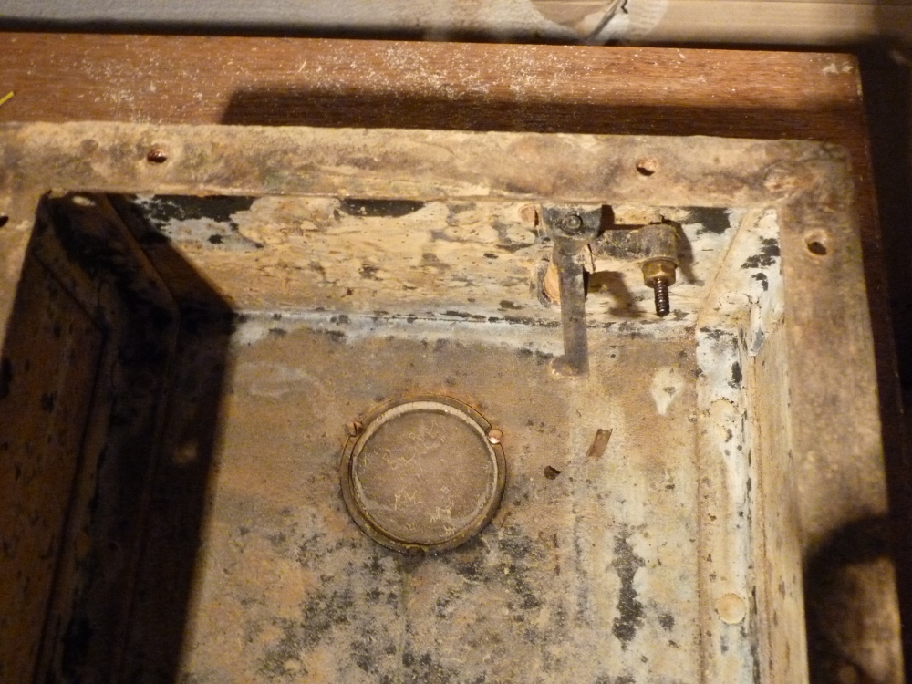
Because of the locked bolt, it is now impossible to lift the locking weight, as this would push the bolt into the electric lock. But what prevents the bolt's movement? To see this, I removed and opened the electric lock. This picture shows the bolt at the lower left:

Opened electric lock

Two videos show the lock's workings. The first one shows the interaction of three levers in the lower part of the electric lock:
  • The first one, which I move by hand, will push ...
  • ... the second, which in turn will lift the locking disc.
  • The third lever, in the back, causes the actual lock by falling behind a link between the two long bars which carry the bolt we saw above.

Internal levers of electric lock

The following video shows the actions inside the electric lock during locking and unlocking:

  • Locking starts—as explained above—by pulling the bolt out of the lock. The first and second inside levers lift the locking disc. A bolt at the acute green end of the disc gets hooked into a U hook which holds the disc in its raised position. At the same time, the third inside lever falls behind the link bar, so that the bars to the bolt are now locked in their forward position.
  • Either the train (via a treadle) or the station master (via a button on the platform) can activate a solenoid behind the locking disc. The solenoid picks up an armature (which I simulate with my finger) and releases the disc. It falls down and, via the second internal lever, lifts the third lever, which opens the way back for the link bar and hence the bars with the bolt. The locking weight lever therefore can be lifted to release the fouling bar lever, whose reversal in turn releases the route bar.

Locking and releasing

On the top of the electric lock, there is an additional, sealed key. Like the solenoid, this key moves the armature and hence allows a route to be unlocked in case of a malfunction or when a train is cancelled after the route has been locked:

Auxiliary key

Auxiliary key lever

Finally, here is a link to a picture of a similar lever frame preserved at Windischgarsten (the neighbor station of Steyrling):

http://www.wandern.com/land/at/oberoesterreich/urlaubsregion-pyhrn-priel/ausflugsziele/kultur/eisenbahnmuseum.html

Also the museums at Ljubljana (Slovenia) and Hradec Králové (Czechia) have 12SA frames—however, none of the photos I have seen at at stellwerke.pechstein.net seems to show an electric lock like mine and the one from Windischgarsten.

Sunday, March 10, 2013

My Austrian type 12SA lever frame: Exclusions between routes

The locking table shows that many routes exclude each other. There are only a few pairs of routes that are possible at the same time:
  • Li-E1 and Re-A1 (through-train on main track no.1 from left to right)
  • Re-E1 and Li-A1 (through-train on main track no.1 from right to left)
  • Li-A1 and Re-A2; or Li-A2 and Re-A1 (leaving from different tracks into different directions after a meet)
and also (even though it is probably useless in practice, but poses no risk)
  • Li-A1 and Re-A1; or Li-A2 and Re-A2 (leaving from the same track into different directions)
All other exclusions are accomplished by one of the following three possibilities:
(a) simple exclusion, when two incompatible routes are on the same route bar;
(b) special exclusion, where a custom-purpose mechanical lock prevents locking two incompatible routes;
(c) as a special case, this 12SA allows some pairs of routes to be locked, but it is not possible to clear both signals! (This is done for the routes E2 and A2 on both sides.)

In principle, there is a fourth possibility:
(d) Two routes are incompatible when a route element (usually points) is not in the same position for both routes. In this station, this criterion would prevent the pairs E1+E2 and A1+A2 on both sides. However, these pairs are already excluded because of (a)!

Why did the designers of the 12SA not place entry and exit route for one track on the same route bar, i.e., use criterion (d)? After all, this would have saved this special mechanical exclusions for case (b) above! In many other types of interlocking, like the Austrian standard type 5007, but also the Austrian electro-mechanical types 42733 and EM55, this was done quite often. But there is a problem with this assignment of routes to route bars: If two routes behind a single signal (e.g. a home signal!) are placed on different route bars, this requires the mechanical equivalent of a logical "or". After all, the signal lever must be free to move if one or the other route bar has moved from its normal position. Examples of such "mechanical ors" are the "neutral bar" (Neutralschieber) of the 5007 or "group locks" ("Gruppenverschluss") and "group drive" ("Gruppenantrieb") of the German "Einheits-Type". However, such a "mechanical or" is a tricky element; and not at all advisable for the rugged type 12SA, which was usually located on the platform, where it had to cope with snow and ice and rain. Therefore, putting routes behind one signal on the same route bar and using additional devices for special exclusion actually simplified the locking apparatus!

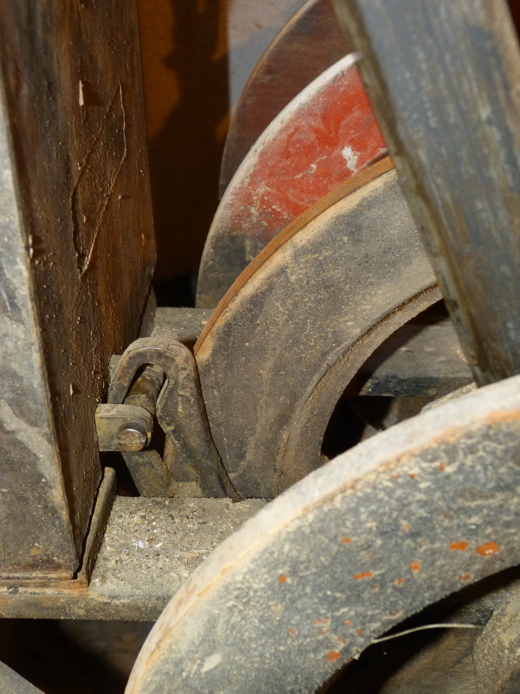
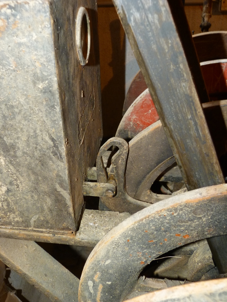
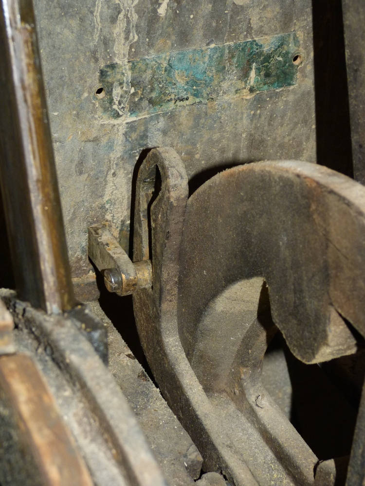
Let us take a closer look at these special exclusions: My lever frame has three of them, of two different types. One of them lurked at the bottom of a picture shown in the posting about locking points levers:


Then the route bar is shifted left or right, the exclusion turns by about 45 degrees:


Seen from below:


The route bars whose movement is to be prevent contain stops, which cannot move when the hooks of the exclusion point upwards. The following picture (which shows the other exclusion of this form) shows such a stop:


The pairs of excluded routes are defined by placing the stops at different locations on the route bars.

The third special exclusion device (which prevents opposing movements) is built differently: The second route bar turns a locking disc via a pin:


The disc lies in front of the front route bar:


When it is turned, a notch on the disc and a corresponding pin on the route bar prevent the movement of the bar:


When, on the other hand, the front route bar has moved left or right, the pin locks the disc in place so that it cannot be turned by the second route bar:


Obviously, this type of special exclusion device fulfills its job like the one explained previously.

Our list of locking concepts has again grown by one entry:

a. Locking pin against locking weight lever (for points lever) or locking bar (for FPL lever)
b. Position check against chain wheel (for points lever)
c. Locking pin hook against chain wheel (for FPL lever)
d. Catches holding nose on chain wheel (for home signal levers)
e. Special exclusion device between route bars

Tuesday, March 5, 2013

My Austrian type 12SA lever frame: Locking the signal levers

Also route levers and signal levers must be interlocked: A signal lever must be locked when the corresponding route lever is in its normal position. On the other hand, when the route lever is a reverse position, the corresponding signal lever is free to move.

Locking the levers for starting signals is simple, because those signals only had a single arm. Therefore, for both routes on which a train could leave the station in the same direction (from the main track or from the loop), this single arm had to be raised. Both such routes are locked by the same route bar, therefore locking the signal is done by a single locking pin. In the normal position of the route bar, it sits below the locking bar of the starting signal lever, which prevents moving the locking weight and hence—via the standard pin on on the locking bar—turning the chain wheel. When the route bar is moved to the left or to the right, the pin no longer locks the bar, and hence the locking weight can be raised and the signal lever be reversed.

The notch that points downwards when the signal lever is reversed is somewhat less deep than the other one: Therefore, the locking bar is a bit lower when the signal is clear, which locks the route bar in place. The following picture shows the locking pin for signal B (there are three visible pins—the one for signal B is the last one):


And for signal C:
"Verschlusstück für Signal C ..." = locking pin for signal C for routes Li-A1 and Li-A2


Both images show additional locking pins for the levers of the starting signals—I'll explain them below.

The locking for home signals, which secure routes into the station, is somewhat more intricate, as the lever must be moved to different positions for the routes E1 and E2: One arm raised for E1, two arms for E2; and of course, only one position must be possible.

For signal A, my interlocking has a lever that is similar to the FPL levers, i.e., it ist moved from the normal position in the middle to an upper or lower position. Locking is accomplished as follows:
  • Interlocking between the route bar and the signal lever is similar to the levers for starting signals.
  • In order to allow the lever only one movement (up or down), but not the opposite one, there are three more locking pins (which look somewhat ad-hoc):
    • On the right side of the chain wheel, there is a long "nose"—here it can be seen when A is clear with a single arm (it seems there was another "nose" on the other side which was sawed away at some time):
    • The route bar contains two catches, which let the nose pass in only one direction, depending on whether the route bar was moved left or right. The following picture was shot along the route bars. A's lever is in its normal position, therefore the nose points down. In the background, one can see the locking pin which prevents the lowering of the locking bar and hence reversing the signal lever:
    • "Verschlussstück für Signal A ..." =  locking pin for signal A for routes Ri-E1 and Ri-E2 "Nase ..." = locking pin on chain wheel of signal lever A
      "Rückhaltung ..." = catch for ...

    For the moment, I skip signal lever D—I hope I find time to explain this double lever in a later posting.

    Anyway, the nose-plus-catch concept has shown us a new locking method. Therefore, our list is now as follows:

    a. Locking pin against locking weight lever (for points lever) or locking bar (for FPL lever)
    b. Position check against chain wheel (for points lever)
    c. Locking pin hook against chain wheel (for FPL lever)
    d. Catches holding nose on chain wheel (for home signal levers)

    Sunday, February 24, 2013

    My Austrian type 12SA lever frame: Locking the FPL levers

    In Austria, the blades of points are secured to the stockrails by blade locks. These are used on virtually all points, even in secondary tracks, and can be run through from the frog even if the points are aligned for the wrong direction (a German explanation of an older type of blade lock can be seen in this posting).

    However, for all facing points which are traversed with 60kph or more, an additional lock is required that firmly locks the blades in place. In mechanical interlockings, these additional lock (called "Riegel") is moved by one or two separate levers. In lieu of another term, I call them FPLs (facing point locks), although they do not at all work like FPLs in England. On my lever frame, the two points in the main track (points no.1 and no.5) required such FPLs; the points in the loop track did not need them, as a train entering the loop would already have slowed to 40 kph or less when travelling over them. The blade locks mentioned above would suffice for securing these point blades.

    Here is the mechanics of locking the FPL lever by the route bars in a 12SA-type interlocking. The normal position of the FPL levers is in the middle, from where they can be moved up or down:
    • When in the normal position, the points are not locked and hence can be reversed by the points lever.
    • When the FPL lever points upwards, the points are locked in the normal position.
    • When the FPL lever points downwards, the points are locked in the reverse position.
    For reasons I do not know, the FPL lever thus moves opposite to the points lever (which points downwards when the points are in the normal position)—here you can see points no.5 locked in reverse. The points lever is on the right and points upwards, the FPL lever is on the left and points downwards:


    The handle of the FPL lever can be pulled out. Here you can see how I lock points no.5 in reverse position (the points are already in the reverse position, their lever points upwards):


    First, I pull out the handle of the FPL lever completely:


    Then I lift the locking weight with my left hand, ...


    ... move the lever downwards, ...


    ... and finally let the locking weight drop so that its locking pin engages in the corresponding notch in the chain (or lever) wheel:


    How do an FPL lever and a route bar lock each other? To find this out, we take a closer look at the levers and the various locking parts. Here is a picture of the lever—three notches are cut into the wheel, one for each lever position:
    • "Ausnehmung und Loch für Plus-Stellung" = notch and hole for upper position
    • "Ausnehmung für Grundstellung des Riegels" = notch for normal position of FPL lever
    • "Ausnehmung für Minus-Stellung" = notch for lower position


    The following picture shows the location of a lever; the lever itself has been removed:


    Here is the same picture, with annotations for the locking parts:
    • "Sperrgewichtshebel" = locking weight lever
    • "linkes Verschlussstück" = left locking pin
    • "Sperrbalken mit Klinke" = locking bar with pin
    • "linkes Verschlussstück" = right locking pin


    In contrast to the points levers (from the previous posting), the locking weight for the FPL levers—and also for all other levers—is situated higher up. The weight lever turns around the same axle as the lever itself. Via an oblong hole at its back end  and a threaded bolt, the weight lever slides the locking bar up and down. On the locking bar, there is a pin which fits into notches on the lever wheel. The left locking pin has the form of a hook (which will move into a hole in the lever wheel); but in addition, this pin also has a lower part which looks like the left locking pin for lock a points lever—we will see this part of the lock in a later picture.

    Here is another picture of the weight lever (with part of the weight visible on the left), its oblong hole, and the vertically sliding locking bar which crosses over the route bars:


    When the FPL lever is in the normal position, route Li-E1 (route bar moves right) is prevented because there is no hole opposite the hook of the left locking pin. Route Li-E2 (route bar moves left) is prevented because the locking bar is in an intermediate position (resulting from the medium-deep notch in the lever wheel), and therefore the high right locking pin collides with the locking bar.

    Route Li-E1

    For this route, the FPL lever must be locked in the upper position. The following picture shows to contact locations for locking (the contour of the lever wheel is a little weird):
    • "Kontur der Hebelrolle" = contour of lever wheel
    • "unterer Teil des linken Verschlussstücks" = lower part of left locking pin


    Lockingis done by the notches in the lever wheel: The lower part of the left locking pin prevents the locking bar from moving downwards (i.e., you cannot lift the locking weight!). The pin of the locking bar sits in the notch of the lever wheel, so that this wheel cannot turn. In addition to this, the hook of the left locking bar sits in the hole of the lever wheel—however, I am quite sure that this is not for locking. After all, pulling forcefully at the FPL lever, one could certainly bend that hook, which is only about 1/3" thick. Therefore, that hooks sits in the hole only loosely.

    Why isn't it possible to select route Li-E2 when the FPL lever is in the upper position? First of all, this is prevented as points no.5 are in the wrong position for this route. But moreover, the right locking pin would collide with the locking bar when the route bar moved to the left.

    Route Li-E2

    For this route, the FPL lever must be locked in the lower position. In this lever position, the pin of the locking bar sits in the lever wheel's deep notch, and therefore the high right locking pin can move below it and thus lock the locking bar (it cannot move downwards):


    Selecting route Li-E1 is prevented similarly to the normal position of the FPL lever: The hook of the left locking pin cannot move into the hole in the lever wheel.

    Lock principles of type 12SA

    The following is a short list which parts take part in mutual lockings in a 12SA-type interlocking. Up to now, we have seen the following combinations—but there will be more!

    a. Locking pin against locking weight lever (for points lever) or locking bar (for FPL lever)
    b. Position check against chain wheel (for points lever)
    c. Locking pin hook against chain wheel (for FPL lever)