Showing posts with label Italy. Show all posts

Friday, May 6, 2022

Austrian block instruments south of Brenner - sensational images from a time long past

When South Tyrol and Trentino fell to Italy after World War I, the Brenner railway down to Ala was equipped with interlockings built by the Südbahnwerke, the interlocking factory the line's owner, both for station and line blocking. The Italian railways FS continued to operate these installations, and they are mentioned in passing in individual documents. The interlockings in the stations are listed under "Apparati Centrali a doppio filo" (i.e. interlockings with double wires), but there were also many Jüdel frames with double wires in Italy, so that one cannot conclude directly from this designation that some frame was a Südbahn frame.

Here are the only two references to these frames I know:

a) On the web site http://www.ilmondodeitreni.it, one finds the entry
3) Apparati Centrali a doppio filo (con bloccamento elettrico degli itinerari, ex Austriaci)
unfortunately without any links.

b) The book "Impianti di Sicurezza" by Vittorio Finzi, published in 2001, contains the following on page 14:
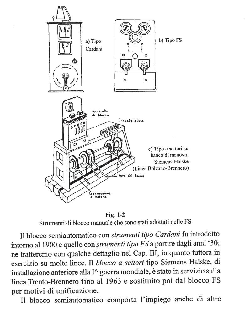

Translated:
The semi-automatic block with Cardani type instruments was introduced around 1900, the FS block is from the 1930s; we will deal with both in detail in Chapter III, as they are still in operation on many lines. The Siemens Halske type line block, installed before World War I, was in operation on the Trento-Brennero line until 1963, when it was replaced by the FS block for reasons of standardisation.
I have not found more than these two mentions so far.

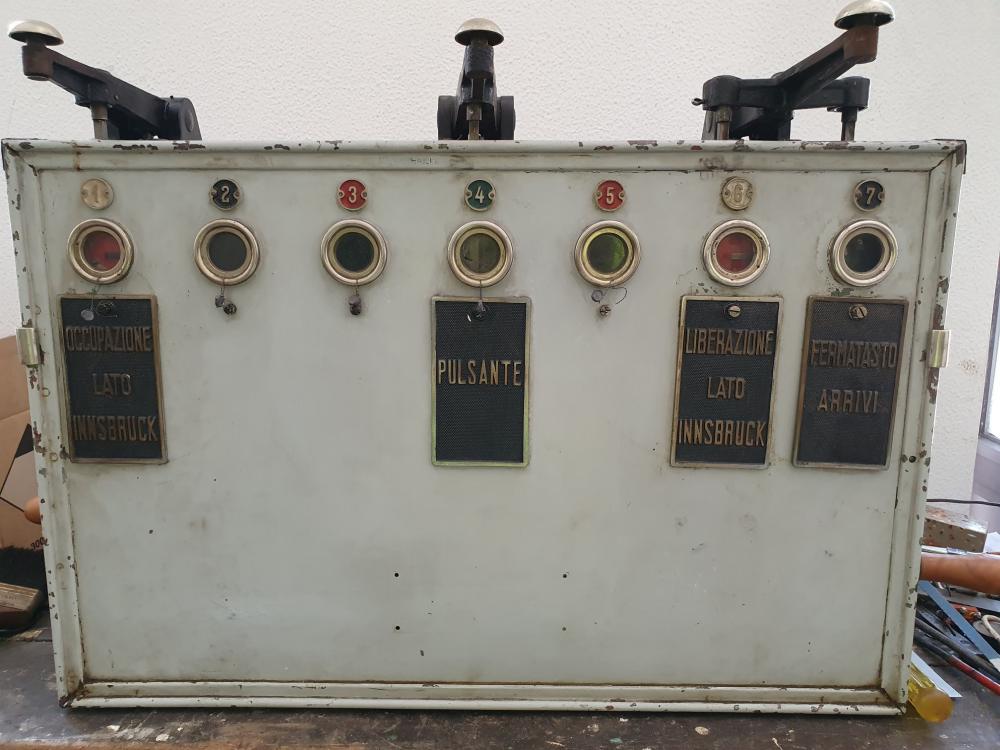
But now Mattia—who found my blog on the internet and who emails me back and forth from time to time; he also has a small railway museum somewhere on the Tendabahn, if I understand it correctly, where I want to visit him—sent me four pictures that are very interesting. I don't know when they were taken; I'll have to talk to him about them from time to time—but here they are:

First image—Mattia writes: "I have had some photo sent to me by a friend who is a signalman in Trento; ... the only remaining apparatus was in the cabin of the Brenner station". The block apparatus is already removed here from the signal box. The designation "Pulsante" under the middle button simply means "push button" or "key" in Italian—not really helpful to understand its function:

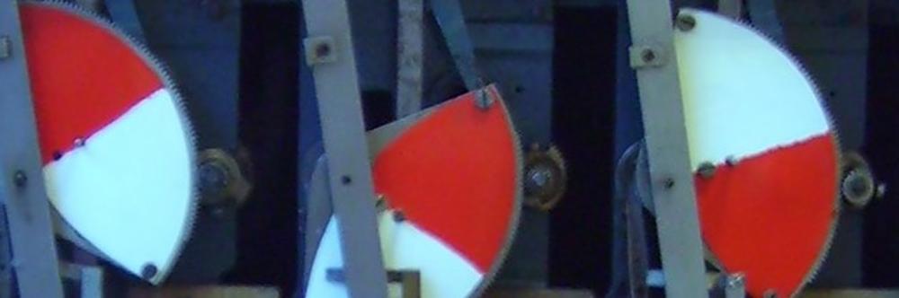
Second and third image—Mattia writes: "I also found a photo from the technical school in Bolzano, it would appear that there is no classic anchor but a toothed wheel".
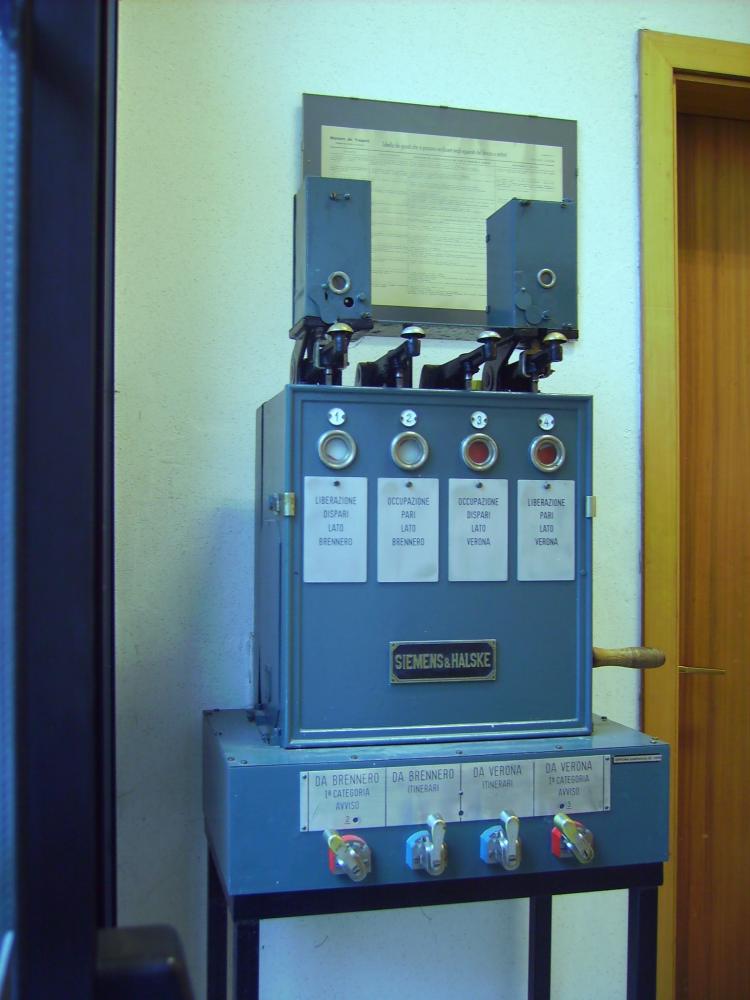
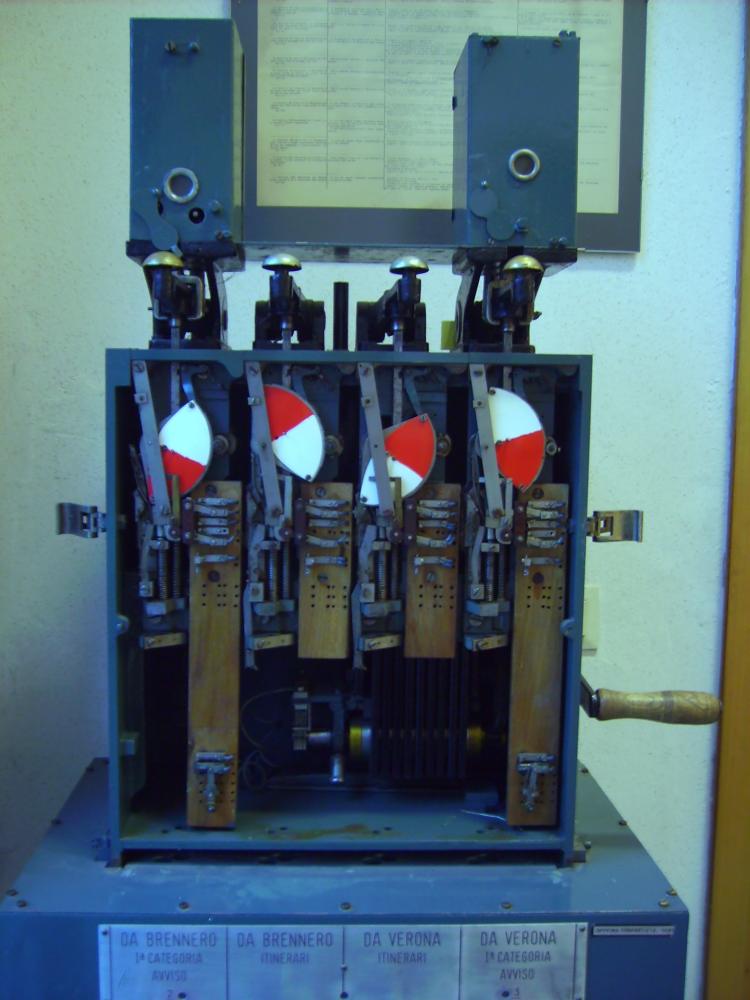


I have enlarged a part of the second picture; the resolution of the pictures is not very high, but you can actually see that the segment discs have a much finer toothing and are motor-driven by a pinion:

Mattia writes: "With regard to the modification in the block, I can confirm that it is as you said, engineer Pacetti was talking about it in the “la Tecnica Professionale” magazine, the blocks have been modified for direct current working, so that there could be no interference due to the alternating current cable for the locomotives."—there seem to exist more documents somewhere. The reason for the modification given probably refers to the fact that the Brenner line was electrified with three-phase current 3.6 kV/16 2/3 Hz from 1928 onwards.

A last picture by Mattia shows the distribution of block systems in Italy in 1939, mentioning the "Blocco a Settori" for the Venezia division, i.e. the Siemens&Halske track block under the designation also from the above mentioned book. Mattia writes: "The graph in the photo shows the kilometers of railway line in which the S&H railway block were used (gray)."
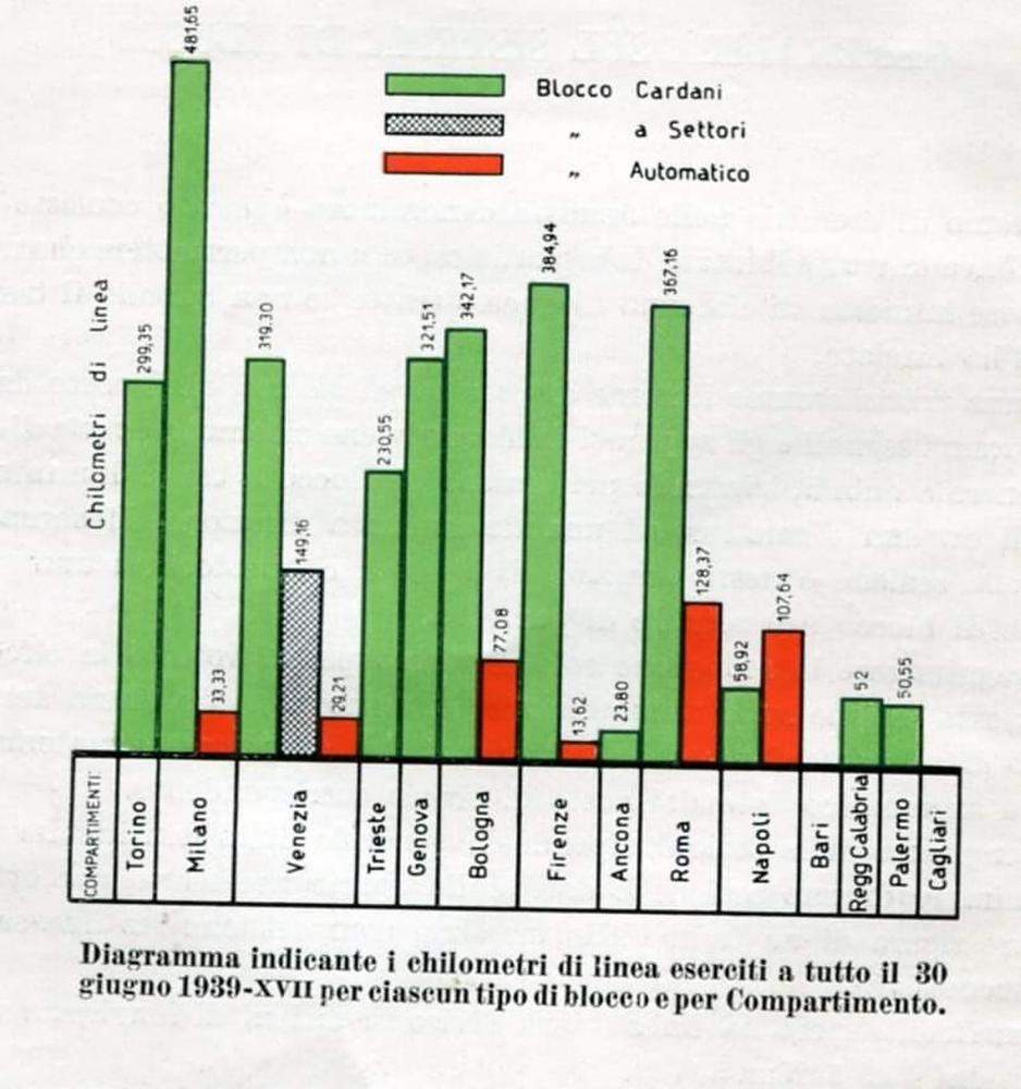

Today's divisions can be seen at this website of Rete Ferroviaria Italiana (RFI). Today Verona is a separate division, in 1939 this area was apparently still assigned to Venezia.

That's it (so far) from this probably largely unknown branch of former Austrian and then Italian safety installations. Many thanks to Mattia for this glimpse into the past and an unexpected technical detail!

Tuesday, March 10, 2020

Puzzling Italian signal levers—final episode: Terni to L'Aquila, 1990

Deutsche Version dieses Postings

Here are my last pictures from our journey to Italy in 1990—they also are puzzling in some respects, like the frames at Pollenza and Cerreto d'Esi. All the following pictures are from stations on the line from Terni to L'Aquila, over the Sella di Corno pass in the Abruzzese Apennines. And on most pictures one can, finally, see men and women who work the frames and control the traffic on that somewhat remote line.

At Marmore, they had two simple levers on a frame for the two home signals. The first picture shows them in the background, near the flag that indicates where the tip of a crossing train should stop:

Lever frame, barrier cranks and stopping flag, Marmore, May 1990

The following image is an enlargement from the previous one. I somehow believe that both levers are seen here in their normal position; and somehow I don't believe it, as the catches would then, very atypically, be at the front of the handles instead of behind them. So, as two trains are meeting here (as can be seen from the red flag), it may very well be that both levers are reversed here.

Question 6: What is the normal position for this type of signal levers?

Lever frame, Marmore, May 1990

The next picture shows the station name, with a steam engine and the symbol of the Ferrovie dello Stato next to it, assembled from many small pebbles. One of the signal levers now has the opposite position; and as with the levers at Cerreto d'Esi or Pollenza, I wonder here also how the single signal wires are coupled to the two-wire levers:

Question 7: How are the single-wire lines attached to this type of levers?

Near the read flag, a railway man is waiting for the train—in the good old times, even such small stations had (at least) two employees working there.

Lever frame, barrier cranks and stopping flag, Marmore, May 1990

The following five or six stations did not have signal levers, but signal cranks of the standard type we have already seen at Asciano. At a few stations, the signal wires were running above the ground (similar to the one I had photographed at Albano), whereas others had already been moved below.

At Greccio, I took a photo of the home signal from our train:

Home signal, Greccio, May 1990

The next image shows the signal cranks and, left of it, a barrier crank. The capo stazione does something with the bell—does he reset a fallen lid?

Barrier crank, signal cranks und capo stazione, Greccio, May 1990

At Contigliano, one can see signal wires above the ground. The cranks are both in normal position, and near them there are no less than four barrier cranks, with all the barriers raised—our departure is still some time away, it seems:

Barrier and signal cranks, Contigliano, May 1990

Also Cittaducale had four barrier cranks and, in addition, a female traffic director. The signal wires were already running below the platform:

Barrier and signal cranks, Cittaducale, May 1990

I also took a photo of the home signal when we departed from the station. It is, atypically, on the right side, with its arm pointing towards the track:

Home signal, Cittaducale, May 1990

Rocca di Corno: The signal wires had been put below the ground, but the old deflection wheels had been left above the cranks:

Signal and barrier cranks, Rocca di Corno, May 1990

Somewhere between Rocca di Corno ("Castle of the horn") and Sella di Corno ("Saddle of the horn", or "horn pass") I took a photo of a telephone pole; the tensioning wires are already quite loose, but the rest is still kept in order:

Telephone lines, which were still in use, Rocca di Corno, May 1990

Next station: Sella di Corno, where the signal wires were also below the ground, and the deflection wheels had also been left in the wall. The meeting train has stopped in fron of the red flag, as the rules require:

ALn668 3335, barrier and signal cranks, Sella di Corno, May 1990

And here is the last station from which I have photographs. On the next image, one can see the distant signal of L'Aquila in a forested narrow valley in the Abruzzese Apennines:

Distant signal, L'Aquila, May 1990

The signal wires left the cranks upwards, towards the still necessary deflection wheels:

Signal cranks, L'Aquila, May 1990

And near the small toilet building, one can see a pole where the signal wires are routed from above the ground to below:

Signal wire routing from above the ground to below, L'Aquila, May 1990

Fine!

Sunday, March 8, 2020

Another electro-mechanical frame in Italy: Macerata, 1990

Deutsche Version dieses Postings

I took only one photograph of the frame at Macerata:

Electro-mechanical frame, Macerata, May 1990

The following two enlargements show a few more details. The levers on the frame are pretty self-explanatory, with the exception of the rightmost one, which should probably be yellow—controlling the distant signal on the Civitanova side; and the light-grey one in the middle, which probably controlled the points visible on the track plan above the starting signal towards Civitanova. The track occupance was shown in the old way, with non-occupied tracks being lighted, and occupied tracks, as well as tracks without track circuits, shown dark—see also the frame at Ciampino:

Electro-mechanical frame, Macerata, May 1990

Track plan, Macerata, May 1990

Outside, I took two more photos of the ubiquitous Fiat rail cars used on those secondary lines:

ALn668 1403, Macerata, May 1990

ALn668 1480, Macerata, May 1990

On our way back to Foligno, I took a last picture of a locomotive, probably at Fabriano:

E646 037, Fabriano(?), May 1990

Thursday, January 16, 2020

More Italian signal lever puzzles - episode 3: Pollenza

Deutsche Version dieses Postings

On our way to Macerata we passed this sign for a level crossing. Far in the background, behind the road overpass, one can see the flashing light actually securing the crossing:

Level crossing warning post, near Tollentino, May 1990

The next picture shows a typical distant light signal with its approach sign. I am not sure where I took this photo:

Distant signal, Tollentino?, May 1990

But here is the next lever frame! The following picture mainly shows mister traffic director in front of it:

Interesting signal lever frame, Pollenza, May 1990

The enlargement below shows more details: On the right, there is a typical crank for barriers. The lever frame proper consists of four signal levers, whose wire rolls are all of the same size, and quite a large one at that. Most probably, the four levers are used for two distants and two home signals. The same size of the wheels could either be the consequence of all signals having compensators (which seems uncommon); or none of them having a compensator (also uncommon); or that the angle the levers are reversed is different for distant and home signals (would be very uncommon). My questions are:
Question 3: How are these levers connected to the single wire lines leading to the signals?
Question 4: Why do the wheels for all signals have the same size? Are there no compensators, or do all signals have compensators, or are the reversal angles different for the levers?
Below the levers, there seem to be some locks, which would then need "some linkage" to lock the wheels (or the handles?) of the signal levers.

Interesting signal lever frame, Pollenza, May 1990

Unfortunately, this is the only picture I have of this type of frame.

On our way to the next station, I took a photo of the distant signal out of the rear of the train:

Distant signal, Pollenza, May 1990

... here it is enlarged, to show to romantic situation between all these trees:

Distant signal, Pollenza, May 1990

And here is a picture of the unoccupied driver's seat at the rear of the diesel railcar:

Driver's seat of an FS ALn 668, Pollenza, May 1990

Wednesday, January 15, 2020

No new puzzles of Italian semaphore levers in episode 2: Matelica und Castelraimondo-Camerino

Deutsche Version dieses Postings

In Matelica I photographed the signals when we arrived at the station:

Distant signal, Matelica, May 1990

Home signal, Matelica, May 1990

Here is a picture of the station buildings, with its massive canopy that had obviously been added later:

Station building, Matelica, May 1990

The lever frame was of the same type as at Cerreto d'Esi:

Lever frame, Matelica, May 1990

Here is an enlargement showing the numerous locks above the levers:

Locks above lever frame, Matelica, May 1990

The following enlargement shows the lower part of the frame, with the wires going down (and letters A, B, C, D on the lever supports). These wires must somehow be connected to the single-wire lines to the signals; with the complication that the wires for the home signals must be pulled when reversing the lever, whereas the wires for the distant signals must be released, because there is this compensator in the line (which in turn requires the different diameters of the rolls). I would have expected that one can see this difference somehow already here, where the wires vanish into the pit below—but this seems not to be the case. The only interesting detail is that the back wires are not parallel, but seem to diverge a little—so they cannot be all vertical, and hence not directly connected to a counterweight. But I cannot guess which sort of mechanics is down there (or somewhere else?) which moves the single wires correctly.

Wires vanishing below the lever frame, Matelica, May 1990

Also Castelraimondo-Camerino had the same type of lever frame, but it is hidden by the signalman on the only picture I took:

Lever frame, Castelraimondo-Camerino, May 1990

Here is an enlargement from the blurred picture:

Lever frame, Castelraimondo-Camerino, May 1990

On leaving the station, I took photos of the signals. Both are mounted on gantries, and both had gotten solar cells, probably for feeding batteries for the signal lamps—an interesting late modernization of these old semaphores:

Home signal on gantry, Castelraimondo-Camerino, May 1990

Distant signal on gantry, Castelraimondo-Camerino, May 1990

So much from these two frames that introduced no new puzzles—more will come in following postings.

Tuesday, January 14, 2020

The puzzles of Italian semaphore levers - episode 1: Cerreto d'Esi

Deutsche Version dieses Postings

In the next few postings, I will show pictures of lever frames and signals shot from the train on two journeys in the Abruzzi. Many of the pictures left me puzzling how the levers were connected to the signals—and I'll share all these puzzles with you, also in the hope that some of you know answers to some of my questions.

Here is my first puzzle picture, of a lever frame at Cerreto d'Esi on the line from Albacina to Macerata and to the Adriatic Sea. Below the picture, I'll ask my first two questions:

Lever frame, Cerreto d'Esi, May 1990

We see a simple lever frame with levers for two home signals and their corresponding distants. Safety is accomplished with simple means: Chains lock the home signal levers to locks that are fastened to the wall; and simple retentions prevent the distant signals from being cleared unless the home signal levers are reversed. The levers turn wheels, and the wire cables are wound around them. But—we will see in a moment that the station had typical semaphores, whose arms where pulled by single wires: What about the second wire end? So my first question is:
Question 1: How are the double-wire levers connected to the single wires to the signal?

Of course, there could be counterweights at the open ends, somewhere below the levers. I am not completely happy about this explanation, first of all, as I would like to see these weights in a drawing or photo; but second, because it is certainly necessary to adjust these counterweights somewhat, for different friction and forces in the single wire lines. How would this work if the weights are suspended in some well below the levers? Again, one could argue that slotted disks as weights could be easily placed there—but this is just some theorizing on my part, which I'd like to be confirmed or rejected.

Next problem: The lines to the distant signals contain compensators. This explains why the rolls on the distant levers are larger than for the home signals—after all, the compensator (as one can see in my posting about Rapolano Terme reduce the wire travel. However, the ratio of the wheel diameters at the compensator is about 2:1; but the ratio here at the lever frame is about 3:2. Why that difference—aren't the distants' arms cleared as far as the home signals' ones?
Question 2: Why is the ratio of the wheels of the levers about 2:3 and not 2:1, as it is at the compensators?

These are all my questions for this posting—more will follow in later ones.

A next photo shows a crank for some barriers:

Crank for barriers, Cerreto d'Esi, May 1990

Back to signals: Leaving the station, I took some pictures of the signals and related facilities. The first one is, of course, the home signal, photographed from the rear end of the train. It is a customary Italian, single-wire pulled semaphore:

Home signal, Cerreto d'Esi, May 1990

Between the home signal and the distant signal, there is the compensator. One can clearly see (at least when magnifying the picture) the single wires, and that the wheel diameter ratio of the compensator is almost exactly 1:2:

Compensator and tensioner, Cerreto d'Esi, May 1990

Next is the distant signal, which I first took from its back side. Again one can see the single wire nicely:

Distant signal, Cerreto d'Esi, May 1990

Then, there is the front side of the distant signal:

Distant signal, Cerreto d'Esi, May 1990

Finally, here are the marker signs indicating the distant's position. Far away, one can see the distant signal a last time:

Distant signal marker signs, Cerreto d'Esi, May 1990

That's it from this small station—I'll show similar, but also somewhat distinct frames in following postings, with their own new puzzles!