Showing posts with label Interlockings. Show all posts

Tuesday, May 10, 2022

"Mechano-electric" interlocking at Greymouth, 1992

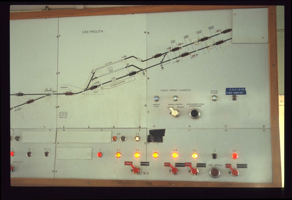
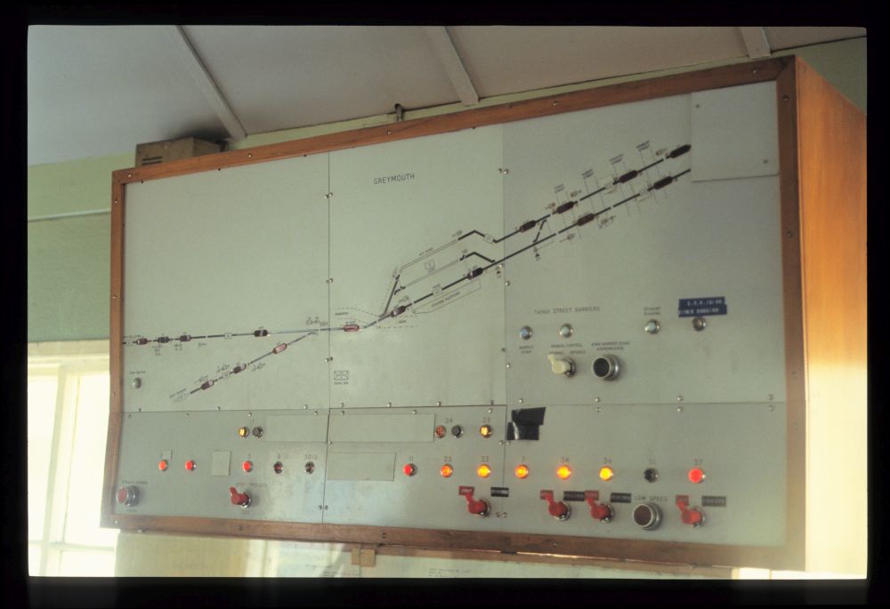
In the considerable time we had to wait in Greymouth for the return trip over Arthur's Pass, I took some pictures at the signal box. The station had lost most of its tracks, as you can see from the last picture in the previous post, but at least three tracks had survived, two tracks went to the yard furtheron, and also the Rapahoe Industrial Line was still connected here:

Track and signal panel, Greymouth, September 1992

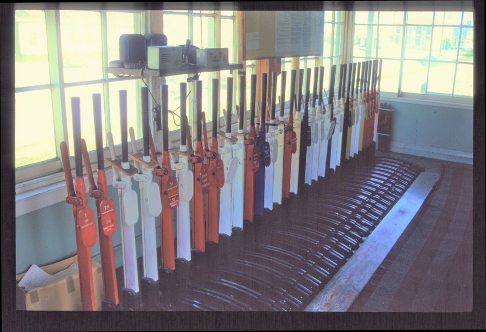
On the lever frame, which looks like a Saxby & Farmer frame to me, there were 32 levers, but 16 of them were unused spares, i.e. not (or most probably not longer) in use:

Lever frame, Greymouth, September 1992

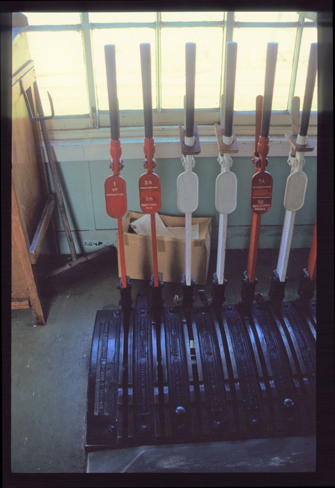
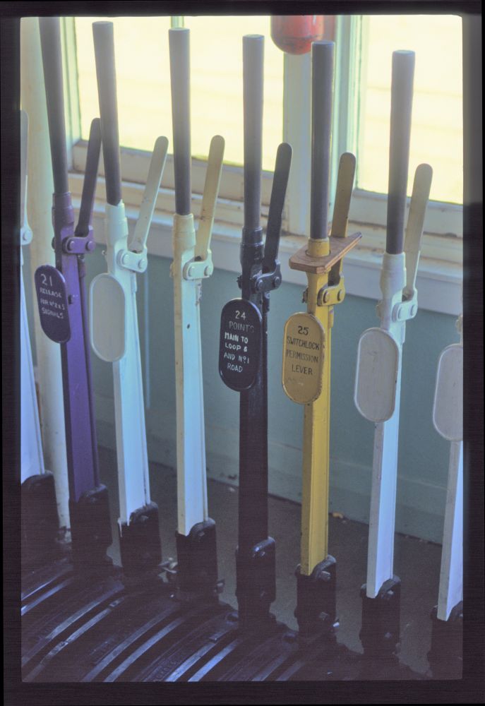
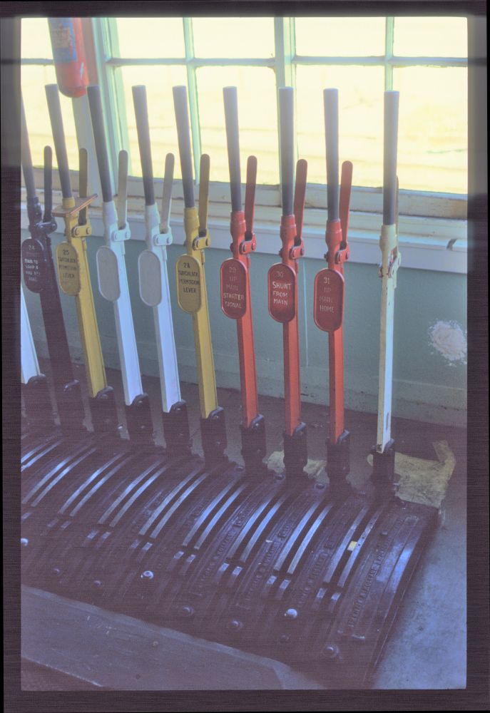
The signals, although operated by levers, were colour light signals throughout, and the points were also electrically operated, as can be seen at the cut-off lever handles. Even with regard to the locks, such interlockings often raise the question of whether they are mechanically or electrically established—I don't know about this interlocking, but in southern England I have seen lever frames that provided all the locking logic electrically via lever locks: I'd like to call such a construction "mechano-electrical" and postulate that Greymouth was nearly such a beast (but I will try to find out what was really still mechanical here). Here are some details of the lever frame:

Levers 1 to 6, Greymouth, September 1992

Levers 21 to 26, Greymouth, September 1992

Levers 24 to 32, Greymouth, September 1992

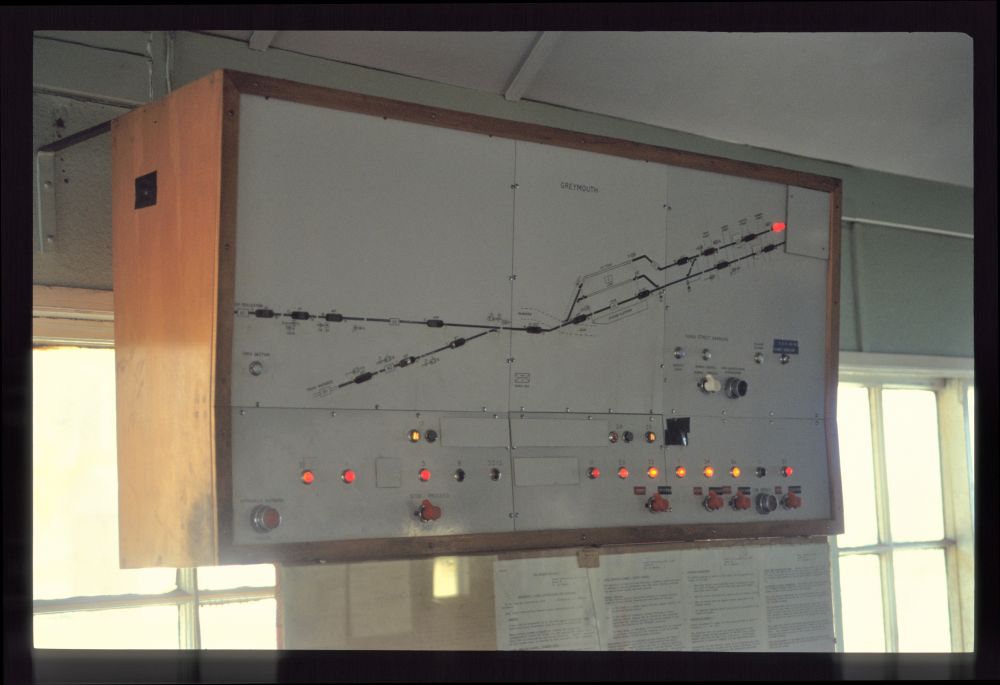
Above the levers, there was the track board already shown above:

Track and signal panel, Greymouth, September 1992

Here, at the top right, you can see the red indication of the returning Tranz-Alpine train set, which will later take us back to Christchurch (without any photos taken by me):

Track and signal panel, Greymouth, September 1992

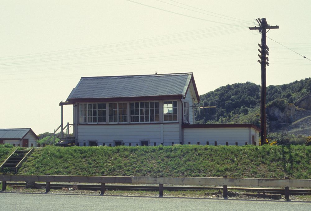
From the outside, the signal box looked like this (and still looks like this—the building is apparently still standing):

Signal box, Greymouth, September 1992

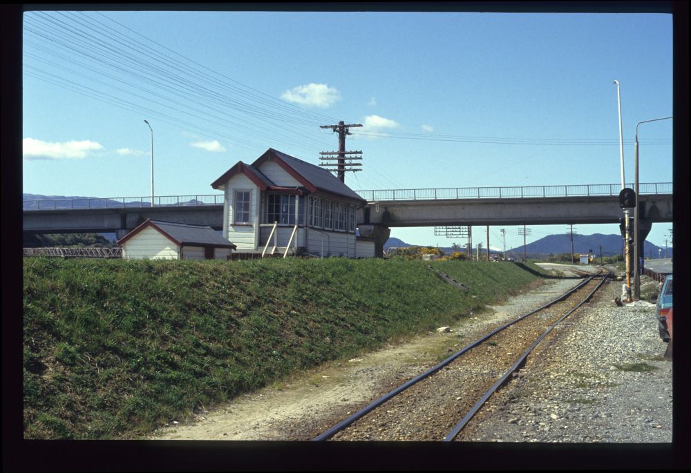
In this picture, looking north, you can see an inner starter on the right, an outer starter far out on the left, and the upper part of the supporting structure of the old Cobden Bridge directly to the right of the signal box building. Unfortunately, I didn't take a single picture of that bridge, because I didn't bother to see what else was interesting nearby:

Signal box, Greymouth, September 1992

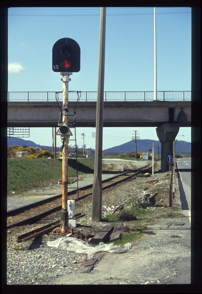
The last picture from Greymouth is the inner starter:

Starting signal 15, Greymouth, September 1992

Saturday, May 7, 2022

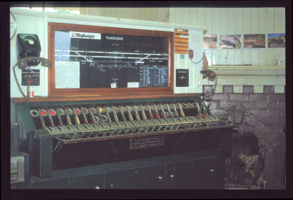
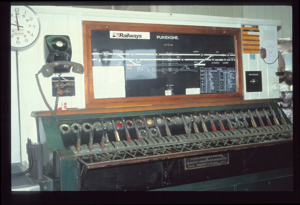
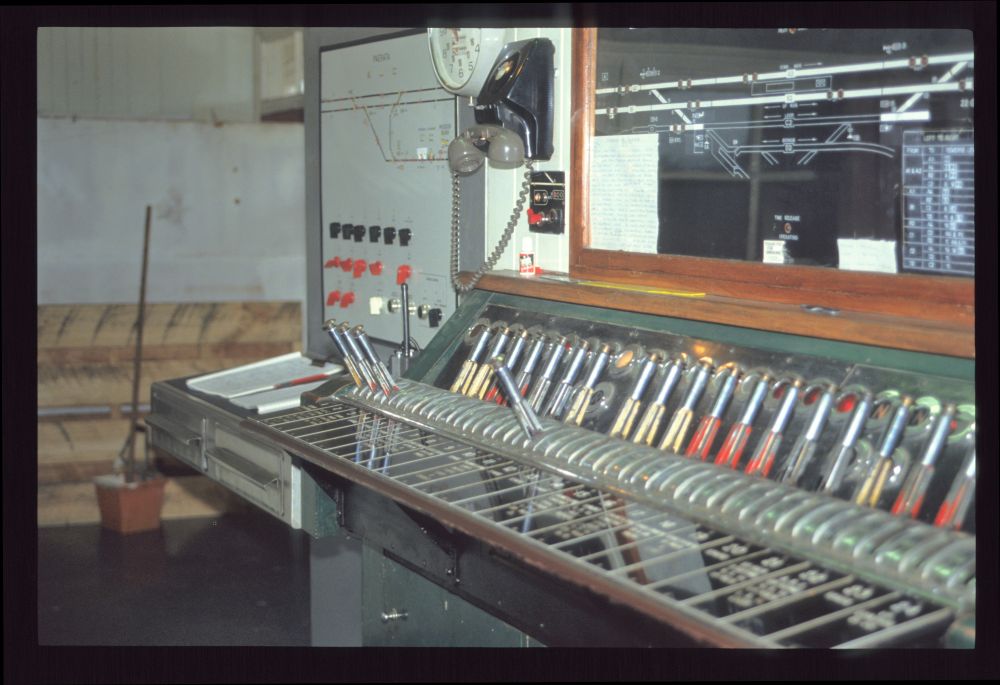
Style A lever frame at Pukekohe, September 1992

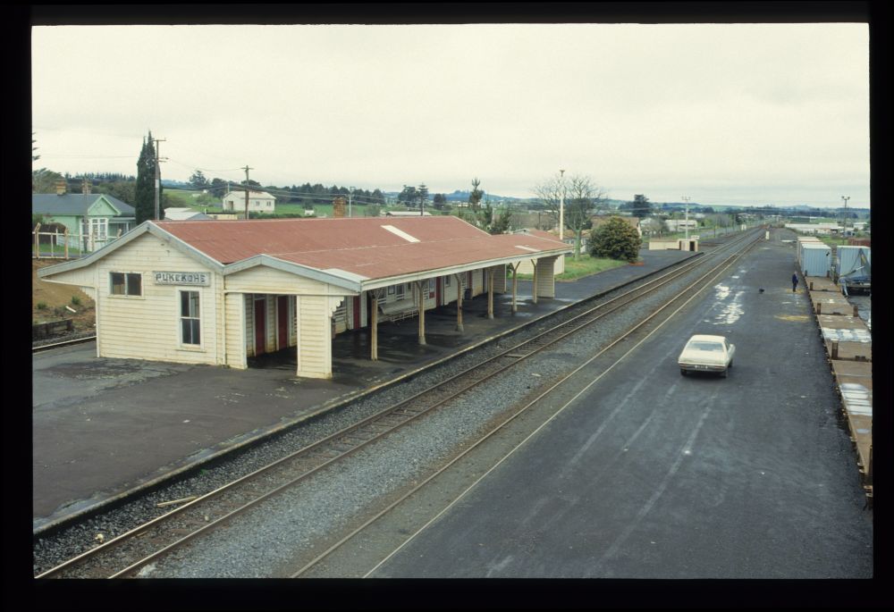
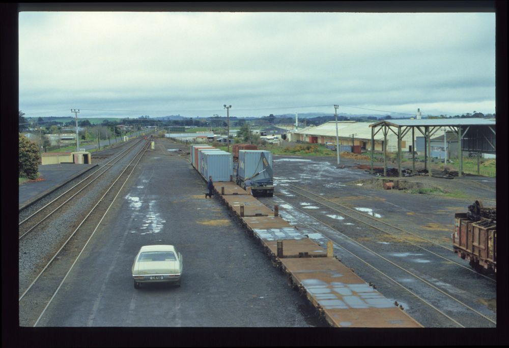
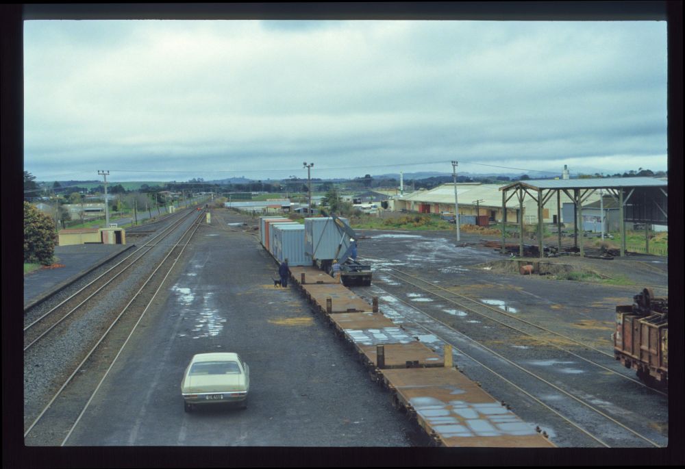
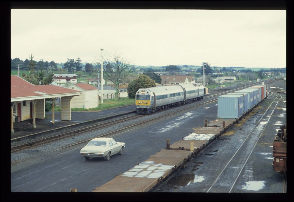
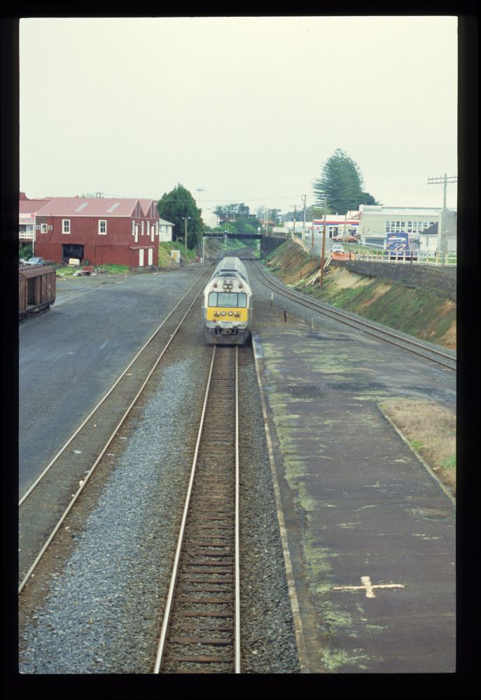
In September 1992, my wife and I visited New Zealand on our honeymoon trip. Among the many slides from there are a few dozen railway pictures, including from two signal boxes. The first, an electromechanical one by McKenzie & Holland of Australia, stood a little south of Auckland at Pukekohe on the North Island Main Trunk, where it survived until November 2017. In Pukekohe there is a pedestrian bridge from which you can see the station area:

Station, Pukekohe, 18.9.1992

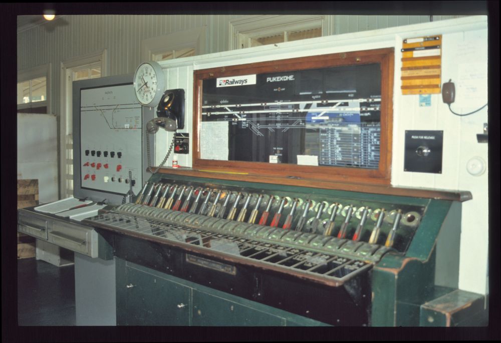
Here are images from Pukekohe's "Style A lever frame":

Lever frame, Pukekohe, 18.9.1992

Lever frame, Pukekohe, 18.9.1992

Lever frame, Pukekohe, 18.9.1992

Lever frame, Pukekohe, 18.9.1992

Lever frame, Pukekohe, 18.9.1992

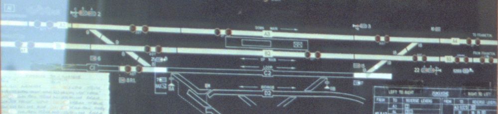
From the third picture I have enlarged the track plan, which is helpful for locating some of the following outside shots:

Track panel, Pukekohe, 18.9.1992

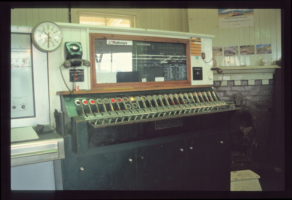
About three kilometres north of Pukekohe, the "Mission Bush Branch" branches off the Norht Island Main Trunk—i.e. the line from Auckland to Wellington—to a steelworks (and to Waiuku). The interlocking for this wye near Paerata was also located at Pukekohe:

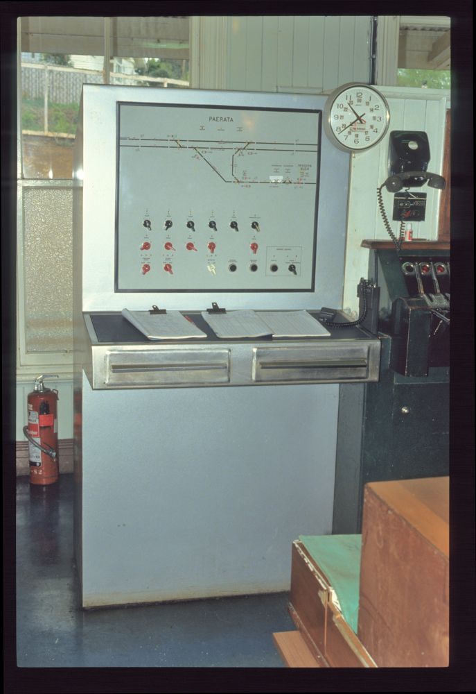
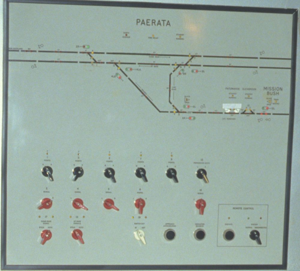
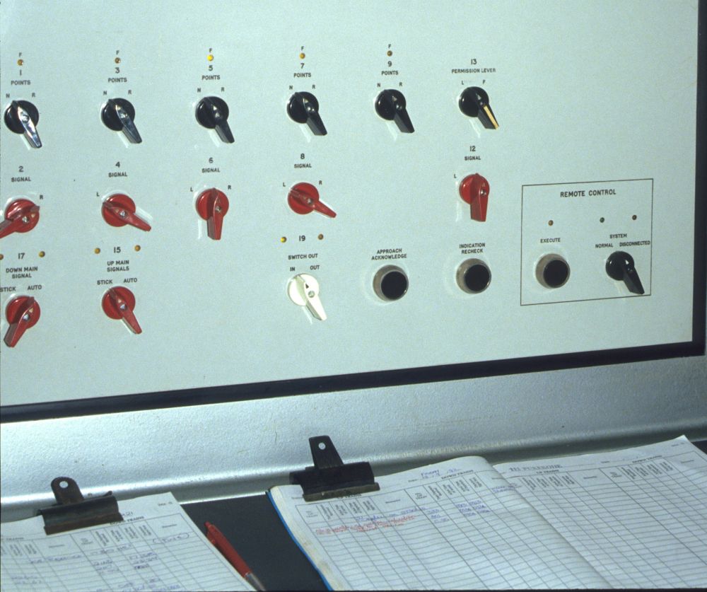
Interlocking panel for wye at Paerata, Pukekohe, 18.9.1992

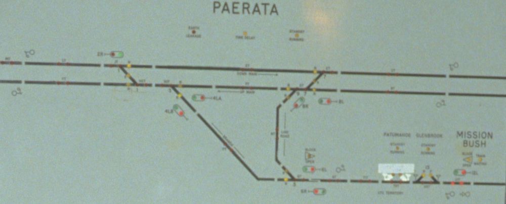
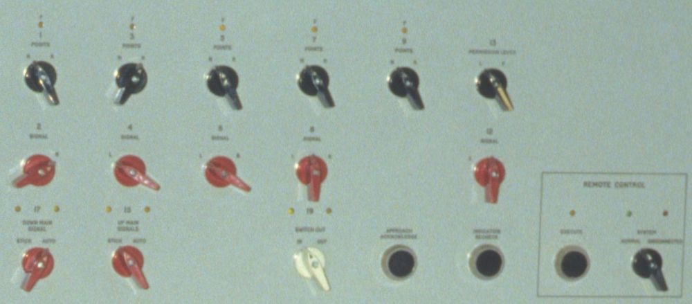
The following pictures show, unfortunately a little blurred, enlarged details of the previous shot:

Interlocking panel for wye at Paerata, Pukekohe, 18.9.1992

Interlocking panel for wye at Paerata, Pukekohe, 18.9.1992

Interlocking panel for wye at Paerata, Pukekohe, 18.9.1992

Interlocking panel for wye at Paerata, Pukekohe, 18.9.1992

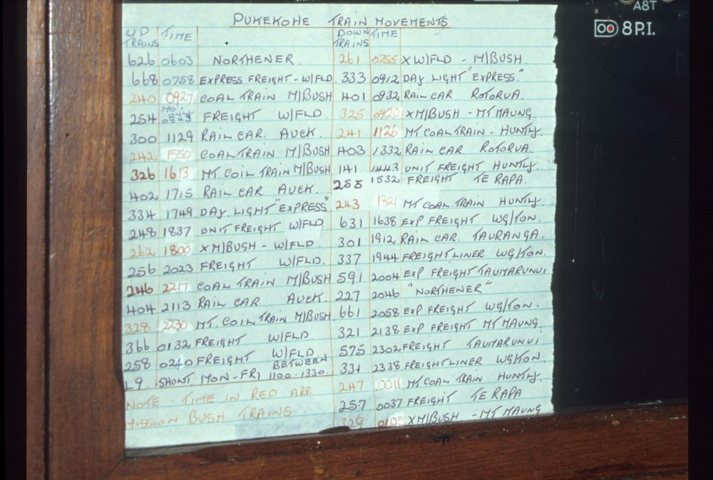
This handwritten timetable was stuck to the track board of the lever bank:

Timetable, Pukekohe, 18.9.1992

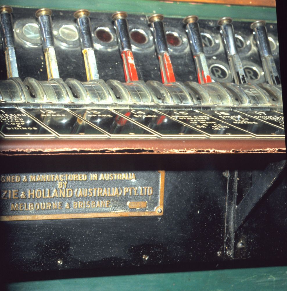
And here is a final detail of the lever bench, unfortunately with the factory plate cut off:

Interlocking frame, Pukekohe, 18.9.1992

Two shots show the direct loading of a container from a truck onto a flat wagon:

Container loading, Pukekohe, 18.9.1992

Container loading, Pukekohe, 18.9.1992

I then set off on a walk to the northern station head, where some shots of outdoor facilities were taken.
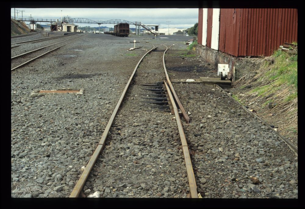
The following turnout 7 is manually set. However, since it is located in a track where it can be traversed by arriving trains against the tips of the points, its tongues must be locked. This is done with a "facing point lock" (FPL), but here it is moved along by the switch lever. In terms of logic, this is similar to the "Zungenprüfer" (literally, "tongue checker") of points for slower speeds used in Central Europe, but an FPL cannot be run through:

Points moving linkage, Pukekohe, 18.9.1992

The switch lever also sets this derailment device, which serves as flank protection:

Derail, Pukekohe, 18.9.1992

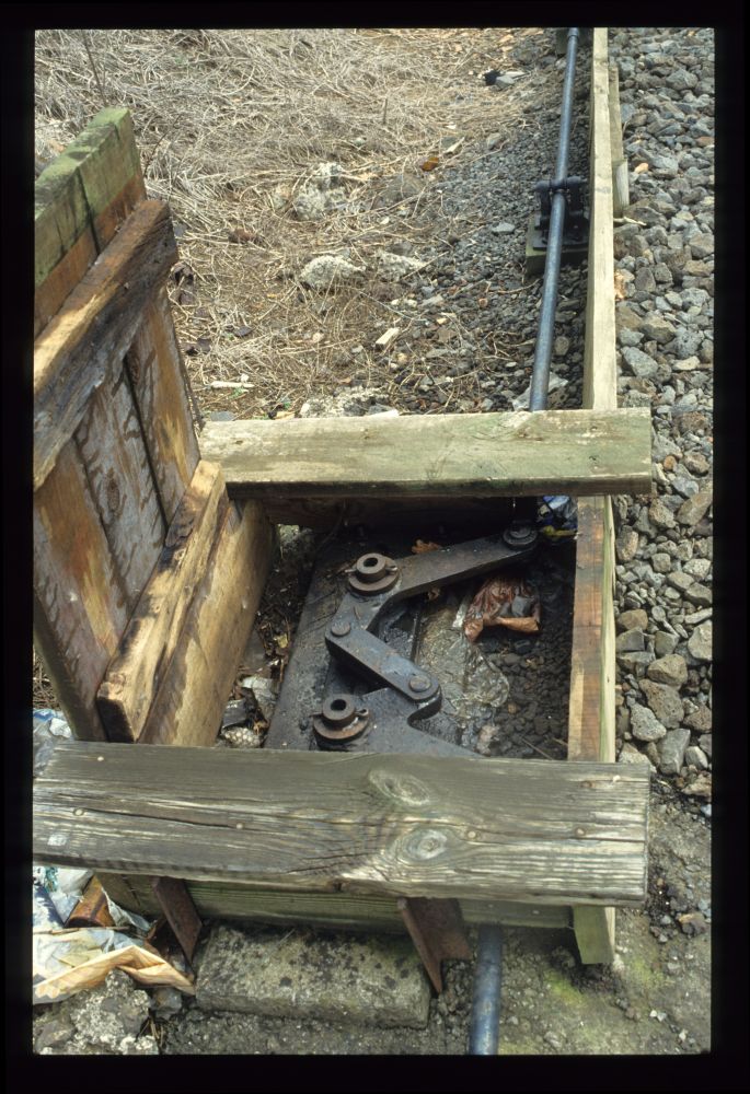
The following compensation lever is connected into the linkage line from the turnout to the derailing device approximately in the middle:

Compensation lever, Pukekohe, 18.9.1992

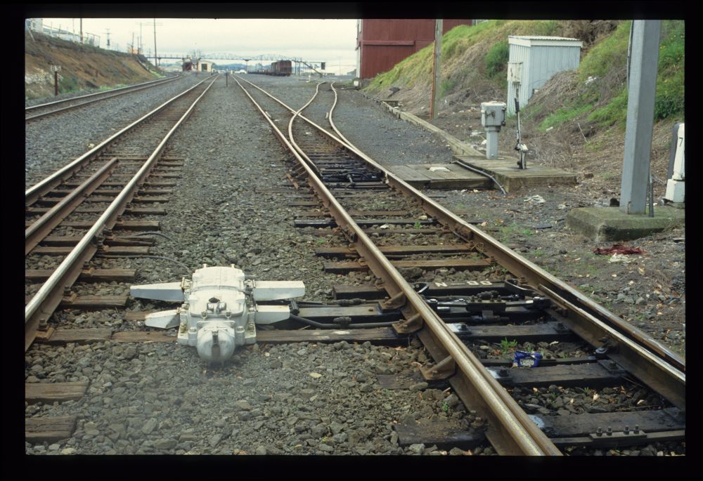
Here one can see an electrically operated turnout controlled by lever 8 (together with the other turnout of the track connection to the track next to it on the left). The turnout 7 from the previous picture can be seen behind it, from which the linkage to the derailer runs:

Points, Pukekohe, 18.9.1992

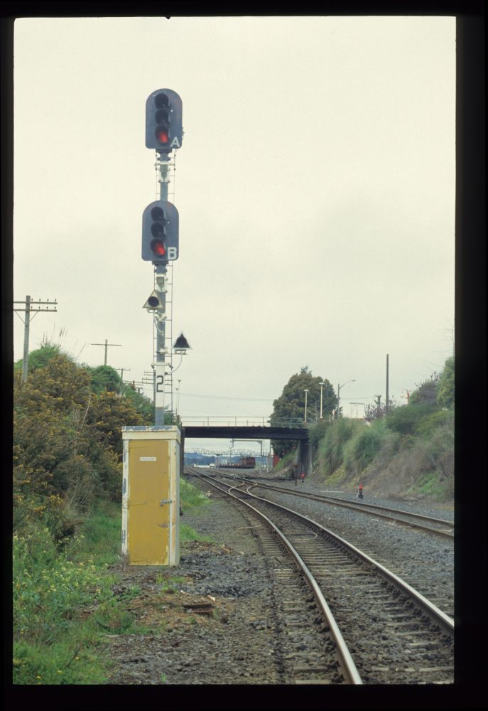
Directly in front of the turnout is the entry signal. It has two signal heads and two auxiliary lights. A rough explanation of New Zealand's speed signalling can be found at nzrailphotos.co.nz. The signal terms seem to be influenced by North America, among others with the cheerful habit of having red lamps glowing at the same time as green or yellow:

Home signal, Pukekohe, 18.9.1992

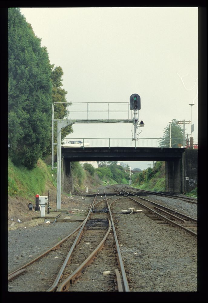
In the opposite direction we see here the starting signal, which is set to free for a train coming soon:

Starting signal, Pukekohe, 18.9.1992

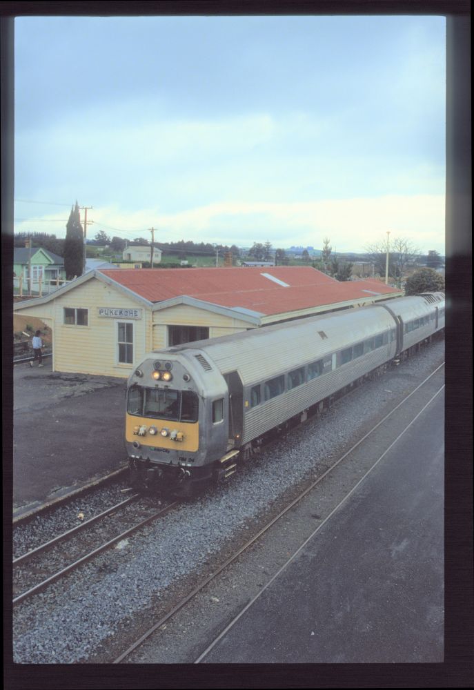
And here is the local train entering and leaving the station:

Railcar NZR RM 24, Pukekohe, 18.9.1992

According to the timetable above, this should be train 300 "Rail Car Auck[land]" at 11:29:

Railcar NZR RM 24, Pukekohe, 18.9.1992

Railcar NZR RM 24, Pukekohe, 18.9.1992

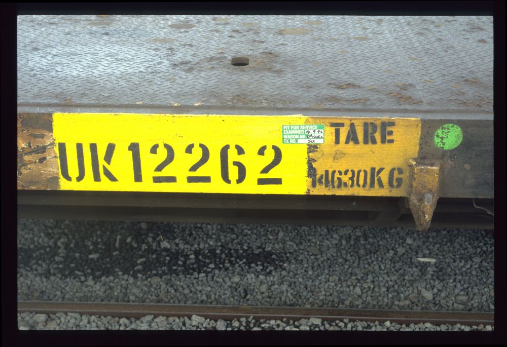
I also photographed the inscriptions on one of the flat wagons for containers:

NZ car inscription UK 12262, Pukekohe, 18.9.1992

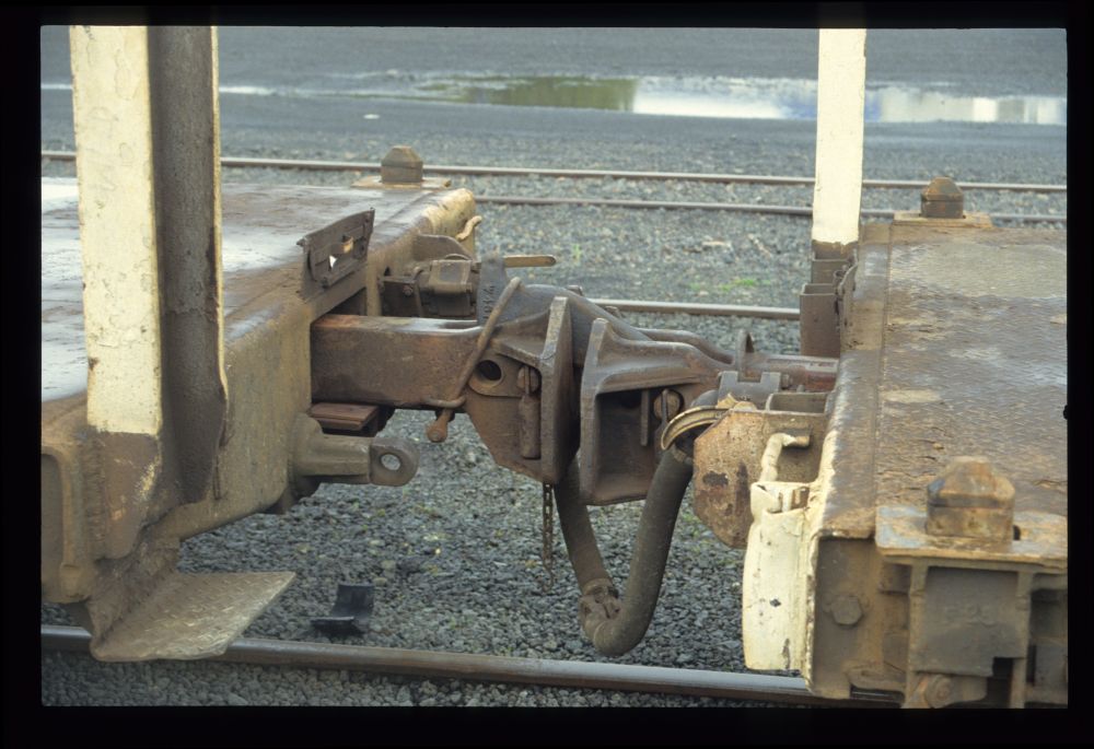
Here you can see the asymmetrical New Zealand coupling for freight wagons, called "Norwegian coupling" because of its origin or also "meat chopper" or "chopper coupling" because of the appearance of the coupling hook –:

Coupling, Pukekohe, 18.9.1992

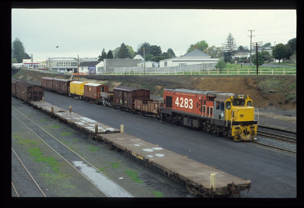
Finally, a work train kindly arrived from the direction of Auckland:

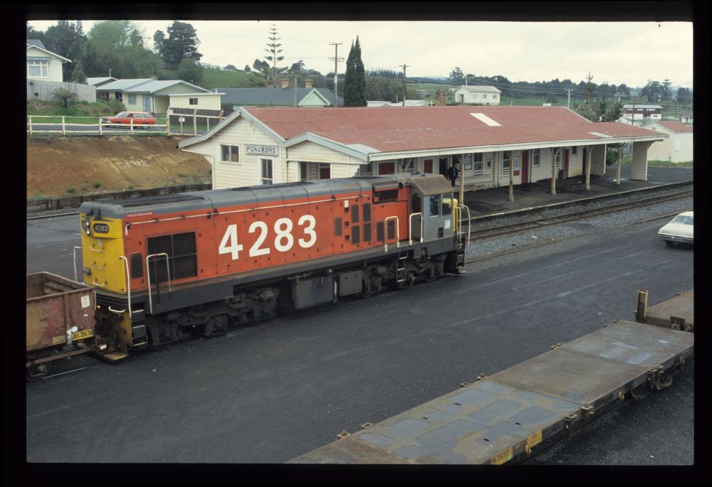
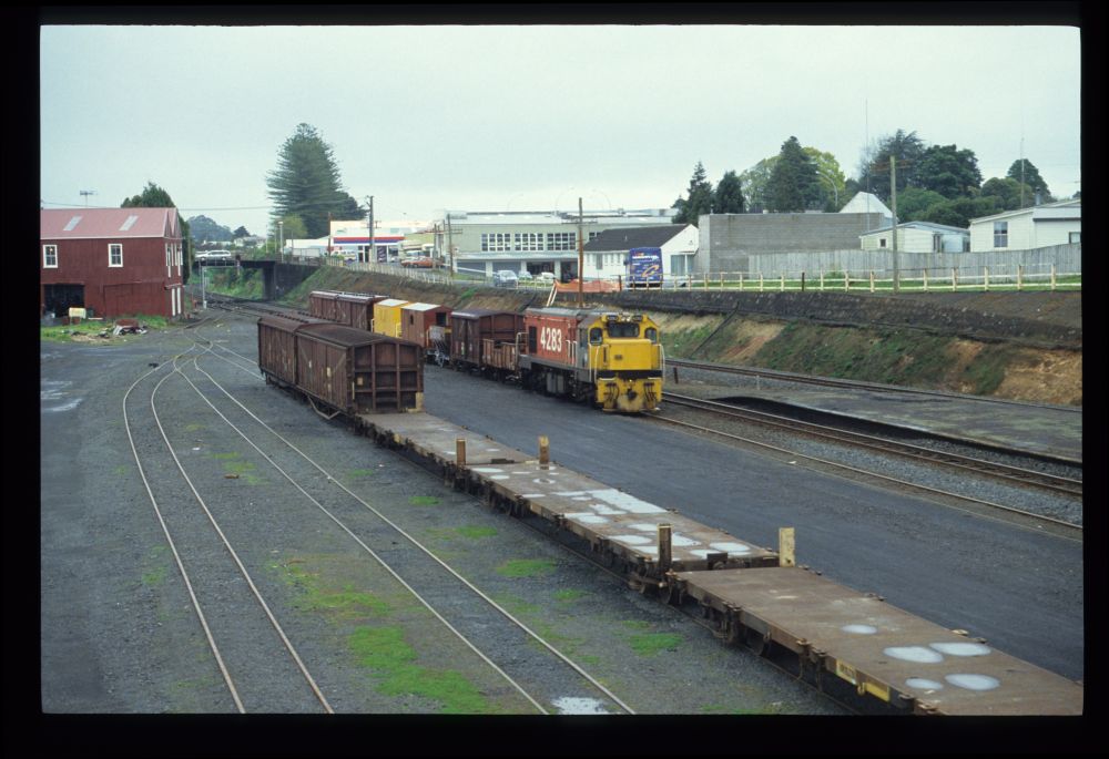
NZR DC 4283 with work train, Pukekohe, 18.9.1992

NZR DC 4283 with work train, Pukekohe, 18.9.1992

NZR DC 4283 with work train, Pukekohe, 18.9.1992

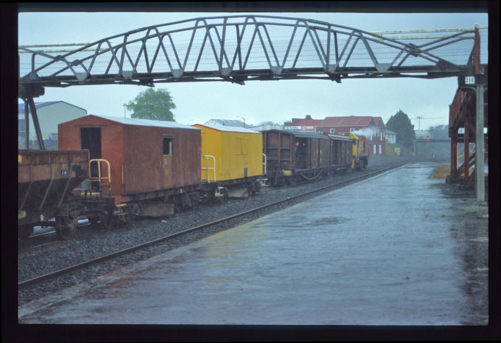
With the sudden onset of rain, shunting work began, but we then left the station:

NZR DC 4283 shunting work train, Pukekohe, 18.9.1992
Friday, May 6, 2022
Austrian block instruments south of Brenner - sensational images from a time long past

When South Tyrol and Trentino fell to Italy after World War I, the Brenner railway down to Ala was equipped with interlockings built by the Südbahnwerke, the interlocking factory the line's owner, both for station and line blocking. The Italian railways FS continued to operate these installations, and they are mentioned in passing in individual documents. The interlockings in the stations are listed under "Apparati Centrali a doppio filo" (i.e. interlockings with double wires), but there were also many Jüdel frames with double wires in Italy, so that one cannot conclude directly from this designation that some frame was a Südbahn frame.

Here are the only two references to these frames I know:

a) On the web site http://www.ilmondodeitreni.it, one finds the entry
3) Apparati Centrali a doppio filo (con bloccamento elettrico degli itinerari, ex Austriaci)
unfortunately without any links.

b) The book "Impianti di Sicurezza" by Vittorio Finzi, published in 2001, contains the following on page 14:


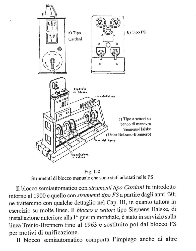
Translated:
The semi-automatic block with Cardani type instruments was introduced around 1900, the FS block is from the 1930s; we will deal with both in detail in Chapter III, as they are still in operation on many lines. The Siemens Halske type line block, installed before World War I, was in operation on the Trento-Brennero line until 1963, when it was replaced by the FS block for reasons of standardisation.
I have not found more than these two mentions so far.

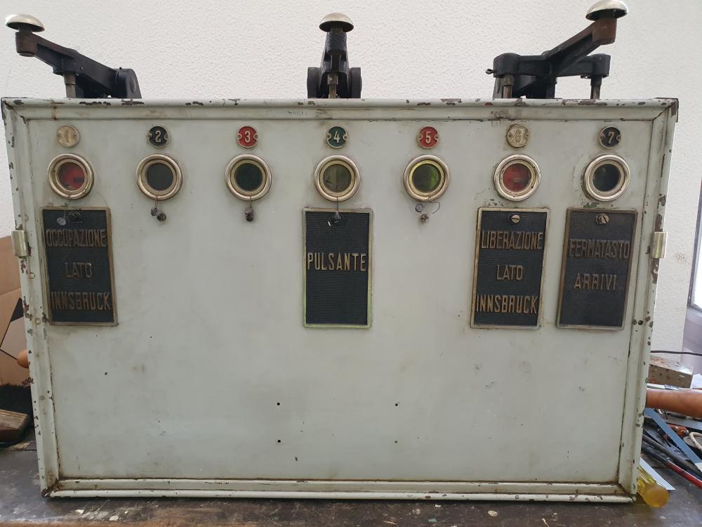
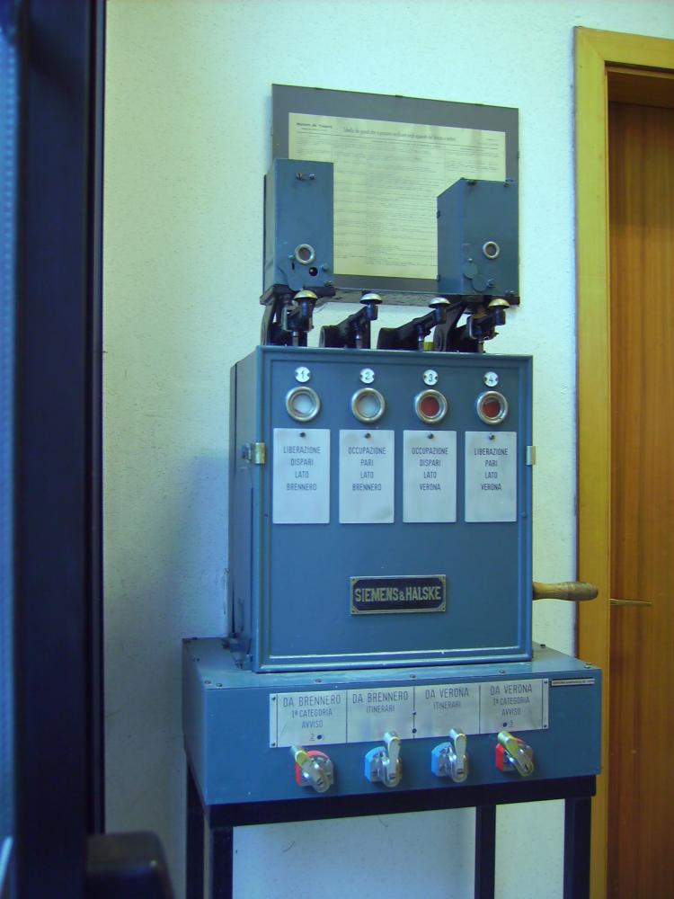
But now Mattia—who found my blog on the internet and who emails me back and forth from time to time; he also has a small railway museum somewhere on the Tendabahn, if I understand it correctly, where I want to visit him—sent me four pictures that are very interesting. I don't know when they were taken; I'll have to talk to him about them from time to time—but here they are:

First image—Mattia writes: "I have had some photo sent to me by a friend who is a signalman in Trento; ... the only remaining apparatus was in the cabin of the Brenner station". The block apparatus is already removed here from the signal box. The designation "Pulsante" under the middle button simply means "push button" or "key" in Italian—not really helpful to understand its function:


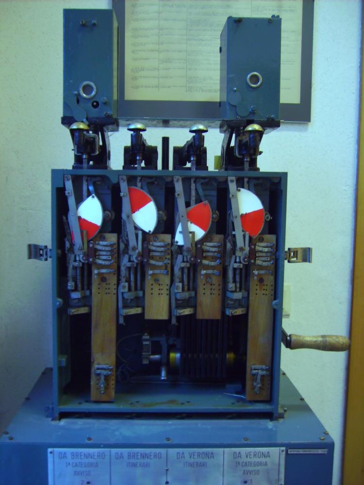
Second and third image—Mattia writes: "I also found a photo from the technical school in Bolzano, it would appear that there is no classic anchor but a toothed wheel".


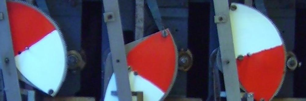
I have enlarged a part of the second picture; the resolution of the pictures is not very high, but you can actually see that the segment discs have a much finer toothing and are motor-driven by a pinion:


Mattia writes: "With regard to the modification in the block, I can confirm that it is as you said, engineer Pacetti was talking about it in the “la Tecnica Professionale” magazine, the blocks have been modified for direct current working, so that there could be no interference due to the alternating current cable for the locomotives."—there seem to exist more documents somewhere. The reason for the modification given probably refers to the fact that the Brenner line was electrified with three-phase current 3.6 kV/16 2/3 Hz from 1928 onwards.

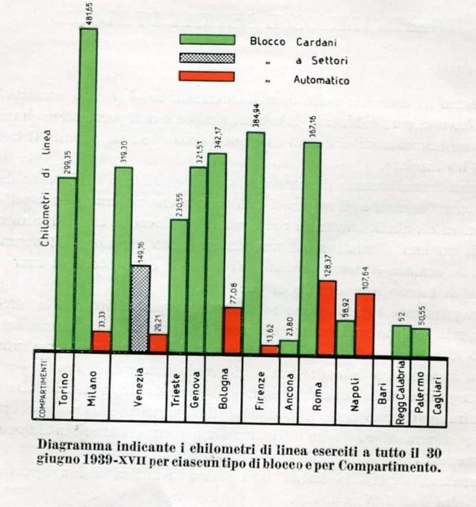
A last picture by Mattia shows the distribution of block systems in Italy in 1939, mentioning the "Blocco a Settori" for the Venezia division, i.e. the Siemens&Halske track block under the designation also from the above mentioned book. Mattia writes: "The graph in the photo shows the kilometers of railway line in which the S&H railway block were used (gray)."


Today's divisions can be seen at this website of Rete Ferroviaria Italiana (RFI). Today Verona is a separate division, in 1939 this area was apparently still assigned to Venezia.

That's it (so far) from this probably largely unknown branch of former Austrian and then Italian safety installations. Many thanks to Mattia for this glimpse into the past and an unexpected technical detail!

Wednesday, May 4, 2022

Molli, 1991

We also visited Bad Doberan in 1991 and took Molli back and forth once or twice. I know that back then you could get on and off the train in Bad Doberan without any problems, and at the walking pace of the train you could also walk ahead of it to take photos—is that still possible today?
Here are some images:

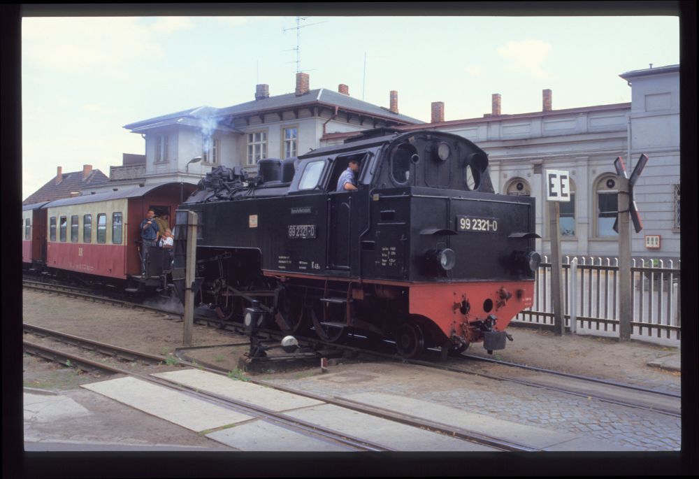
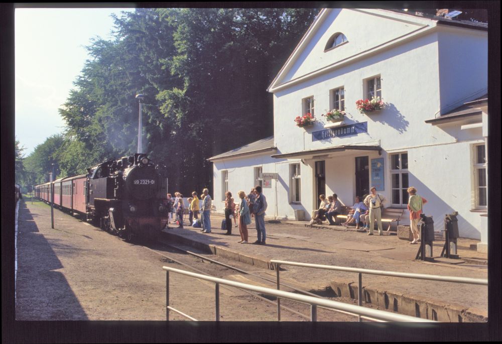
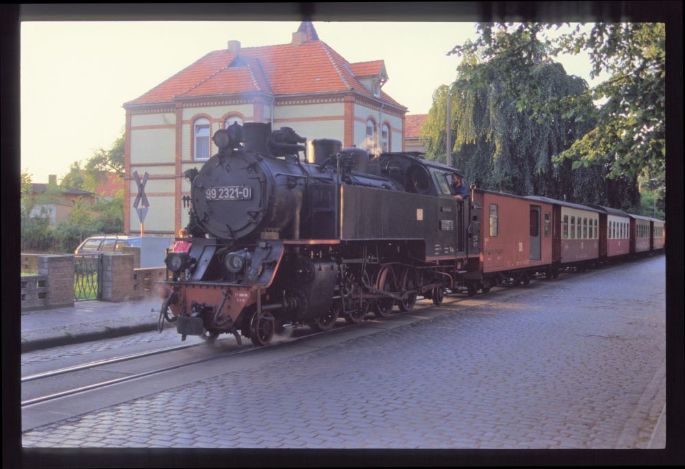
Molli's DR 99 2321, Bad Doberan, August 1991

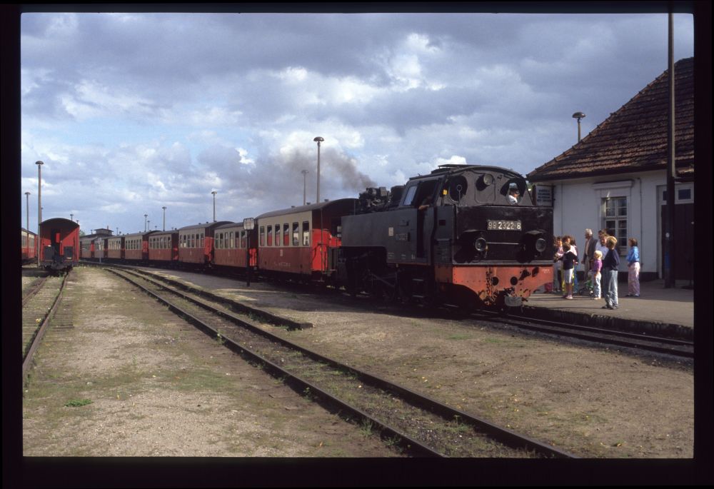
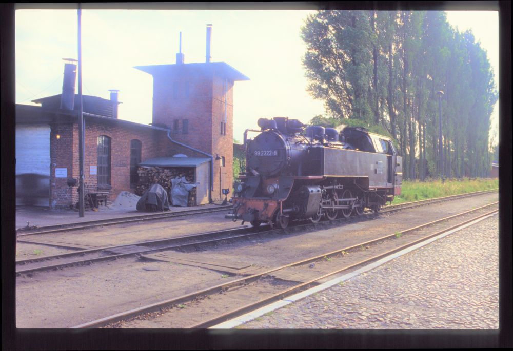
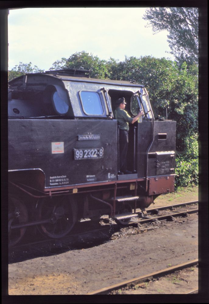
Molli's DR 99 2322, Bad Doberan, August 1991

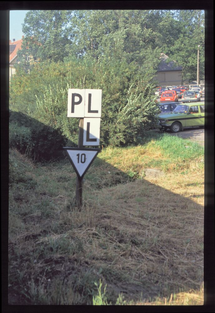
Whistle and bell signal on the Molli, Bad Doberan, August 1991

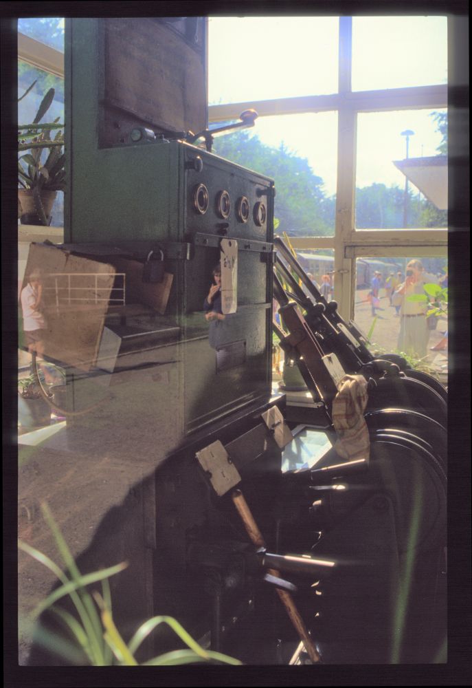
The photo I too of the lever frame at Heiligendamm was taken through a reflecting window, so there are some reflections here. In terms of block instruments, there is just a single block instrument for all routes a1, a2, b1 und b2—thus, only one route can be set up at any one time. As for the levers, we can see
  • two route levers—in the picture, one can see that the right one is reversed to the upper position for locking route b1;
  • two signal levers for the single-armed semaphores A and B—in the picture, the right one is reversed, so home signal B is cleared;
  • and two points levers for points 1 and 4—both are in normal position in the picture, as route b1 leads into the main track.

Lever frame, Heiligendamm, August 1991

Here you can see the train that has arrived on this track:

Molli's DR 99 2321, Heiligendamm, August 1991

Until a few years ago, this home signal stood at the entry to the terminus station Kühlungsborn West, but it had been equipped with a white cross showing that it was no longer in use. In 1991 it was still in operation. You can see here, as in some other pictures in previous postings, that narrow signal masts were erected in many places where they were not actually necessary—obviously the spare parts stock for masts was at some point restricted to narrow masts, which were then (at least partially) used as standard masts:

Home signal A, Kühlungsborn West, August 1991

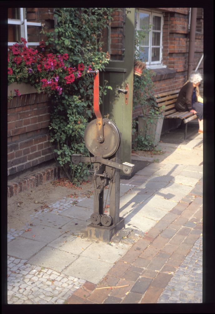
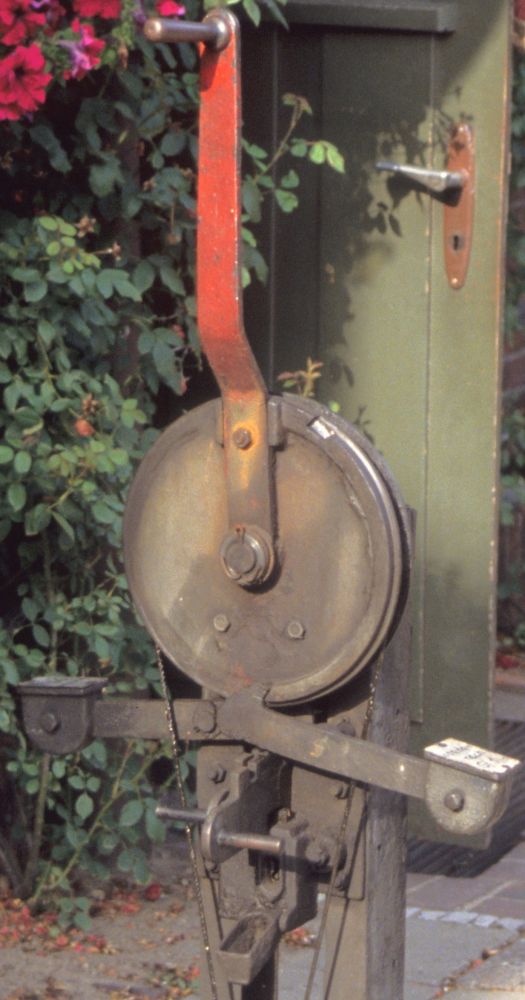
The signal was controlled by this signal lever:

Signal lever, Kühlungsborn West, August 1991

I would think that the lever was flipped in one direction or the other depending on the entry track (1 or 2)—there are at least markings on both drop-in weights. However, there is only one lock below the release slider, which means that a release dependent on the point switch position could probably not have taken place. But maybe there is another lock on the back of the trestle. Maybe someone has a signalling plan that explains how this worked?

Signal lever, Kühlungsborn West, August 1991


Now for some images of Molli steamers:

DR 99 2322, Kühlungsborn West, August 1991

Cleaning the windows on DR 99 2322, Kühlungsborn West, August 1991

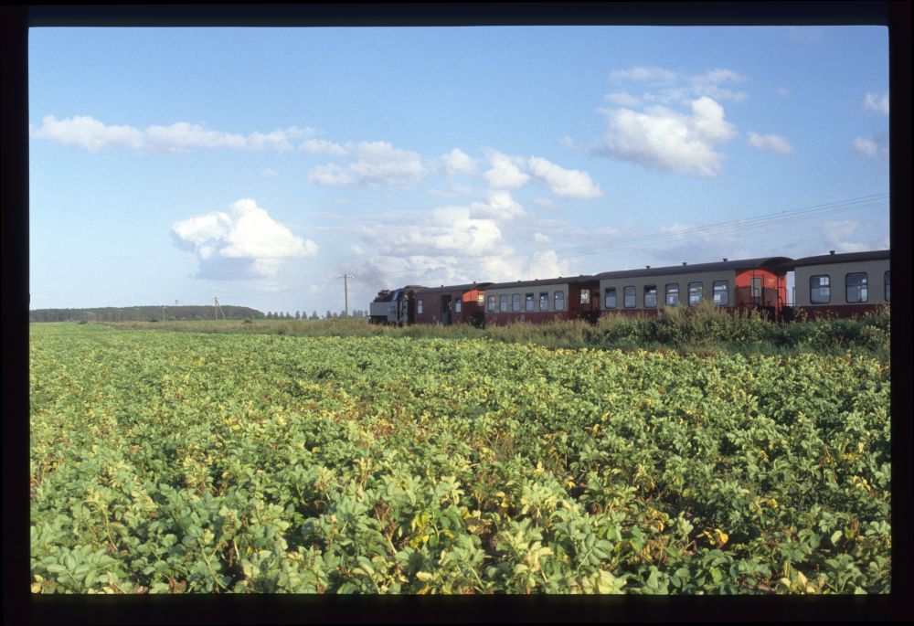
Molli, near Steilküste, August 1991

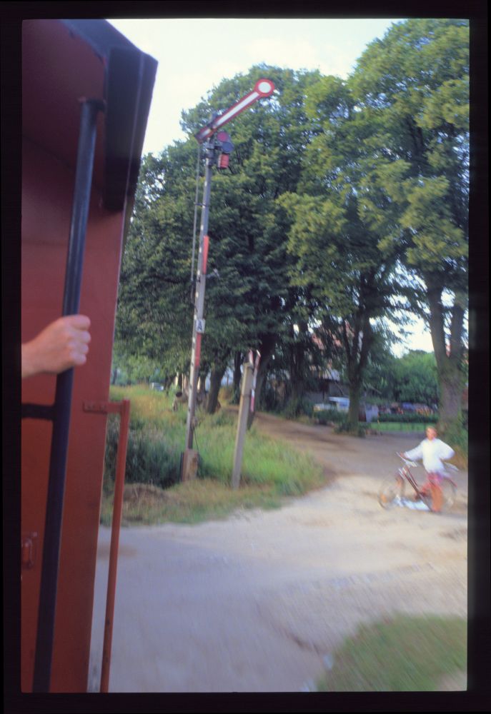
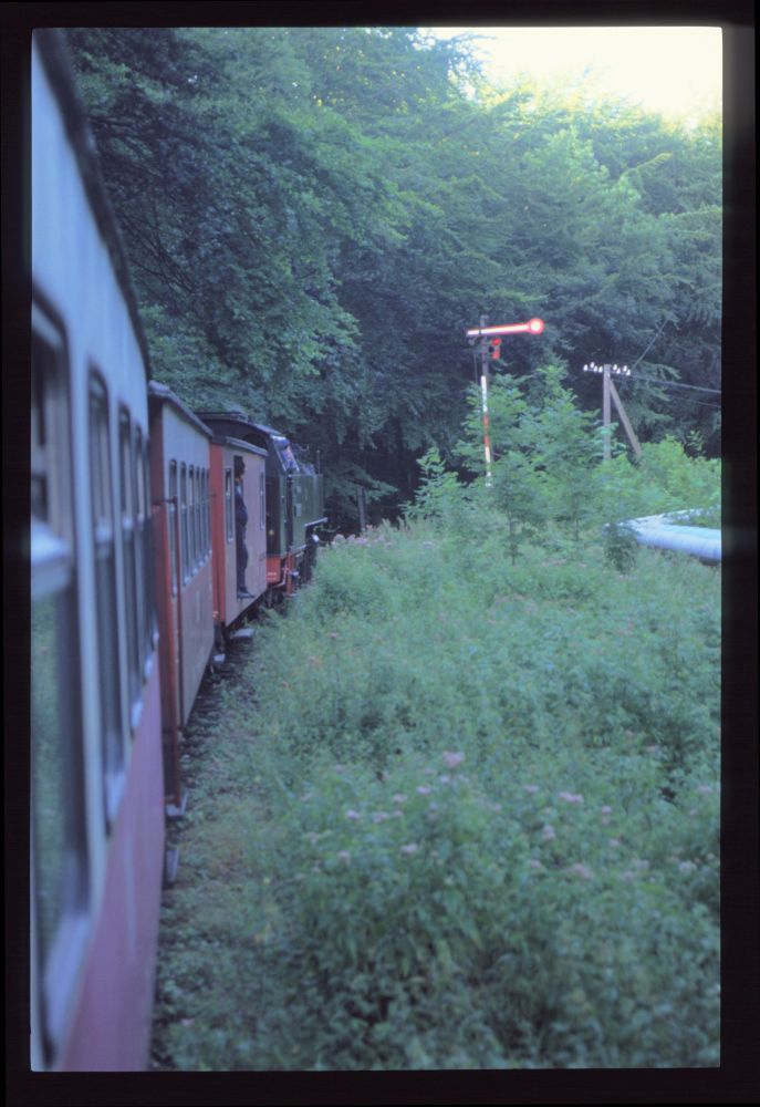
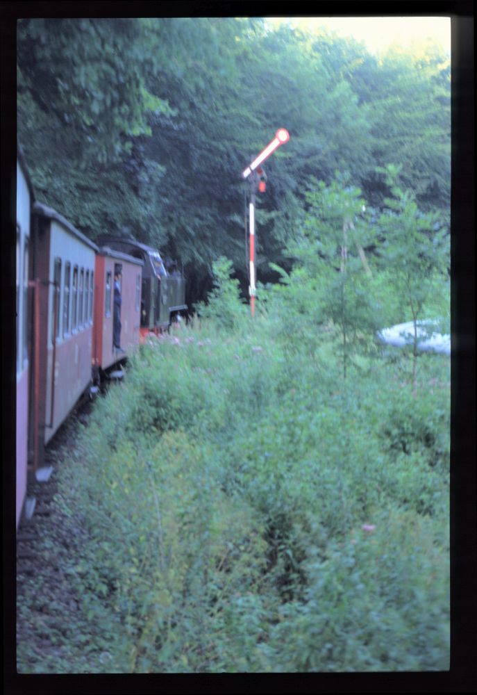
On the return trip, we had to wait in front of the Heiligendamm home signal—presumably the train on track 2 always enters first:

Home signal B from Kühlungsborn, Heiligendamm, August 1991

I only have this blurry photo of the cleared signal, which I show here anyway for the sake of documentation:

Home signal B from Kühlungsborn, Heiligendamm, August 1991

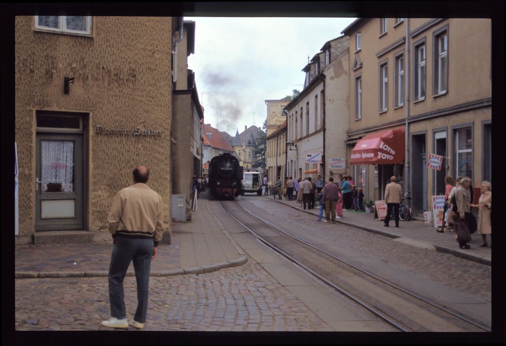
Two more pictures of the famous street running in Bad Doberan:

Molli's DR 99 2321, Bad Doberan, August 1991

Molli's DR 99 2322, Bad Doberan, August 1991

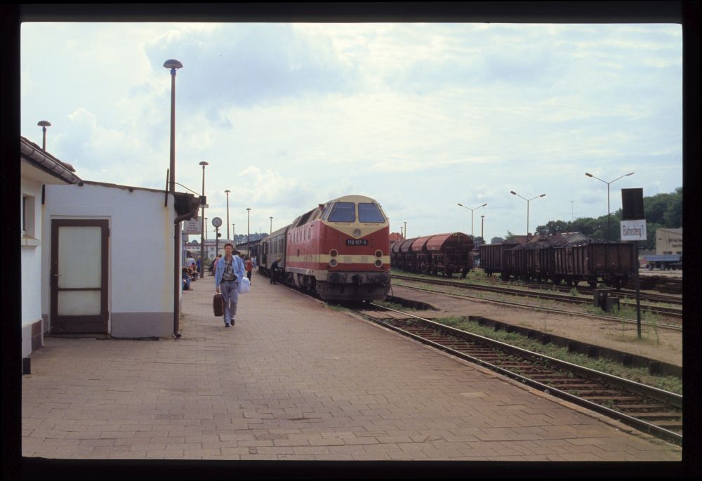
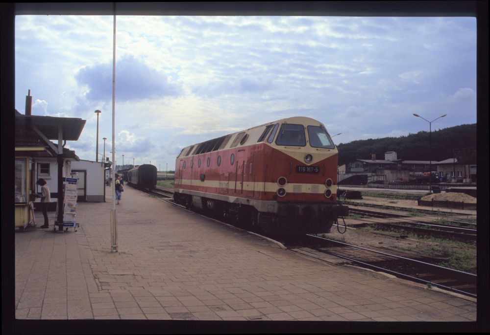
And finally two pictures of a diesel locomotive on the standard gauge side:

DR 119 167, Bad Doberan, August 1991

DR 119 167, Bad Doberan, August 1991

That's it with our pictures from 1991—a few pictures from the Weißeritztalbahn and a small handful of pictures I missed will come in a final posting.