My friend Werner has completed much of the work at his "Sammlung Grafenberg", so in the week before Easter, we did a few first test runs—which was quite much fun! Here are a few photos and videos from this meeting.
Werner has
- completed "Steyrling" (which was the original station controlled by my 12SA lever frame),
- hooked up the semaphore and two sets of points
- and connected the telephones between the original "Absdorf" station and "Steyrling" ...
Not everything was working flawlessly at that time—the semaphore's lower arm was somewhat too low, the tracks were a little wobbly, and the telephone batteries had been depleted through the winter, and/or some contacts were a little corroded.
Since then, all that and more has been fixed:
- There are now double on each side of the wagons and locos,
- the locos have magnets to simulate track circuits,
- the tracks have been screwed down at most places,
- the semaphore's lower arm has been weighted,
- and all the points at "Steyrling" have been hooked up to the frame.
Here are a few videos and photos from the "inauguration meeting"—where I discovered that my knowledge about Austrian train handling procedures has gotten quite rusty over the last 30 years. Thus, we skipped some of the necessary offer-and-accept procedures for single-line working (we convinced ourselves that the model railway's DC supply was a sufficient safety measure against collisions ;-) ).
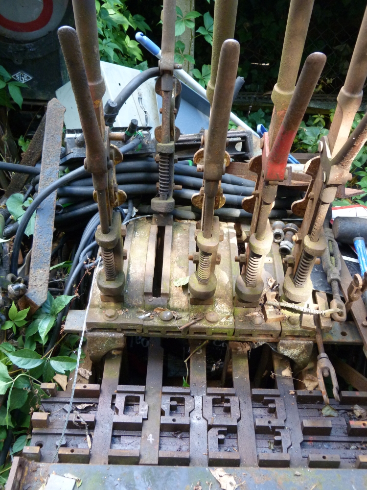
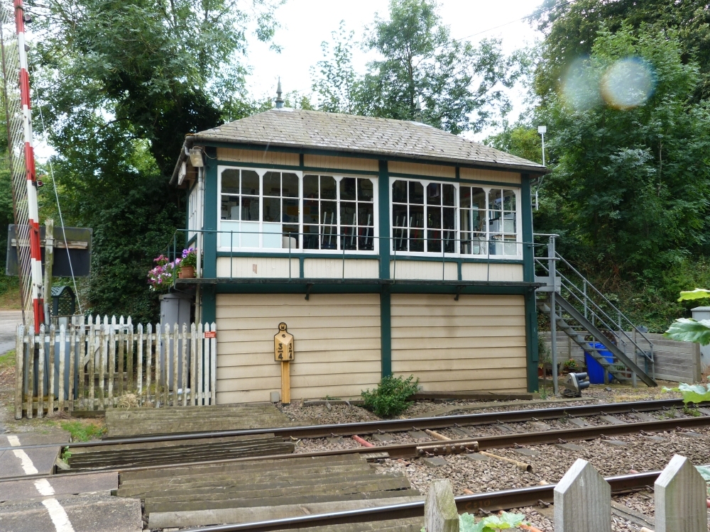
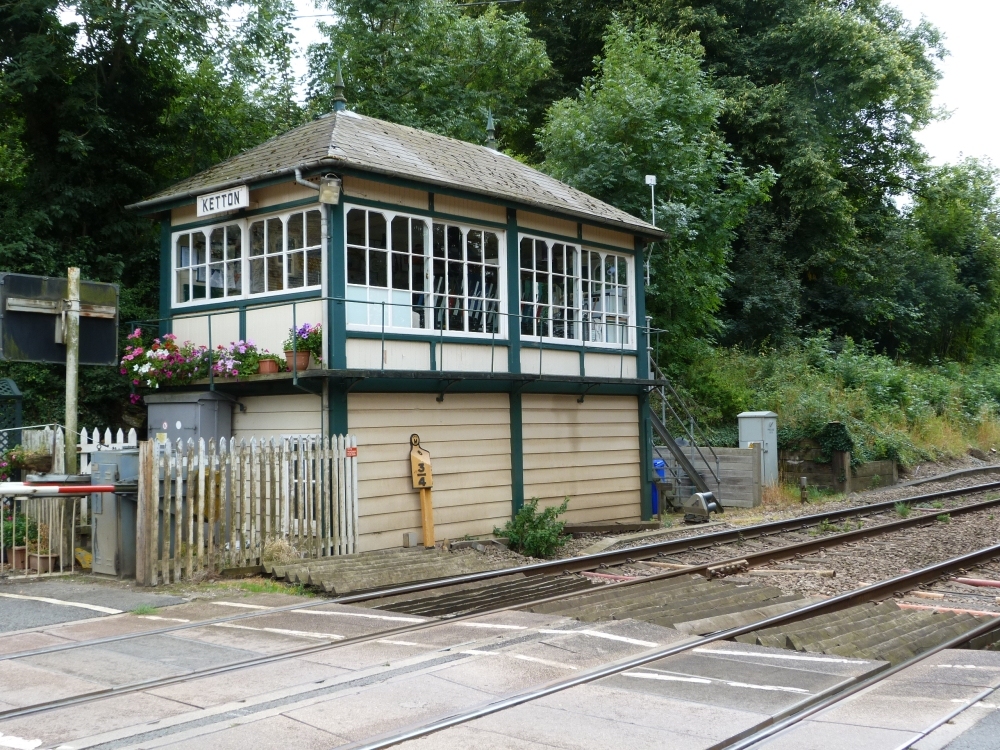
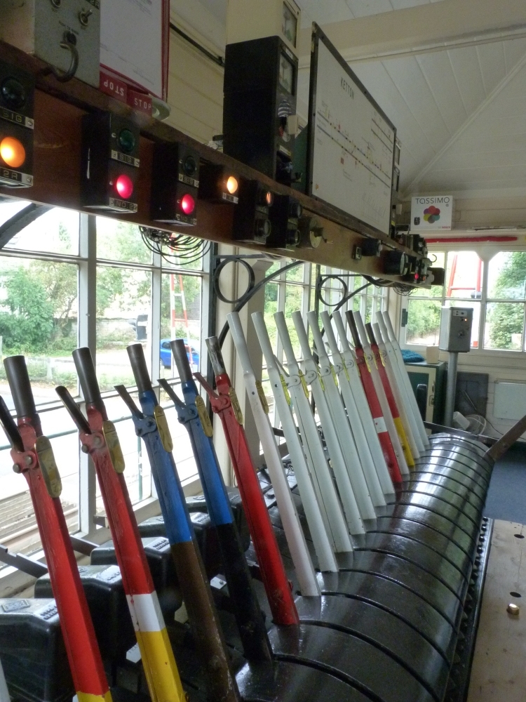
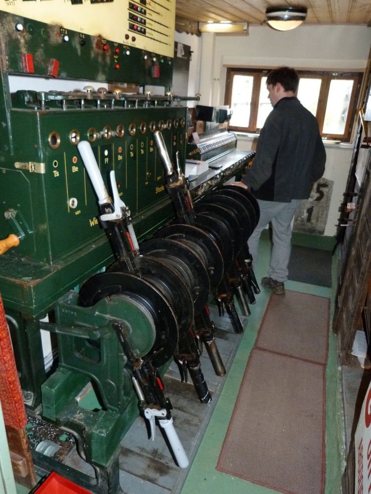
Here is the 12SA frame, now located in an old work hut from the NÖVÖG, which is now "Steyrling"'s signal box:
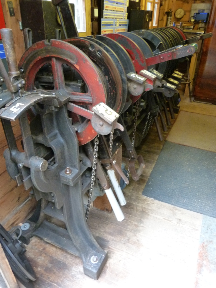
12SA frame "Steyrling", Sammlung Grafenberg, 16.4.2014
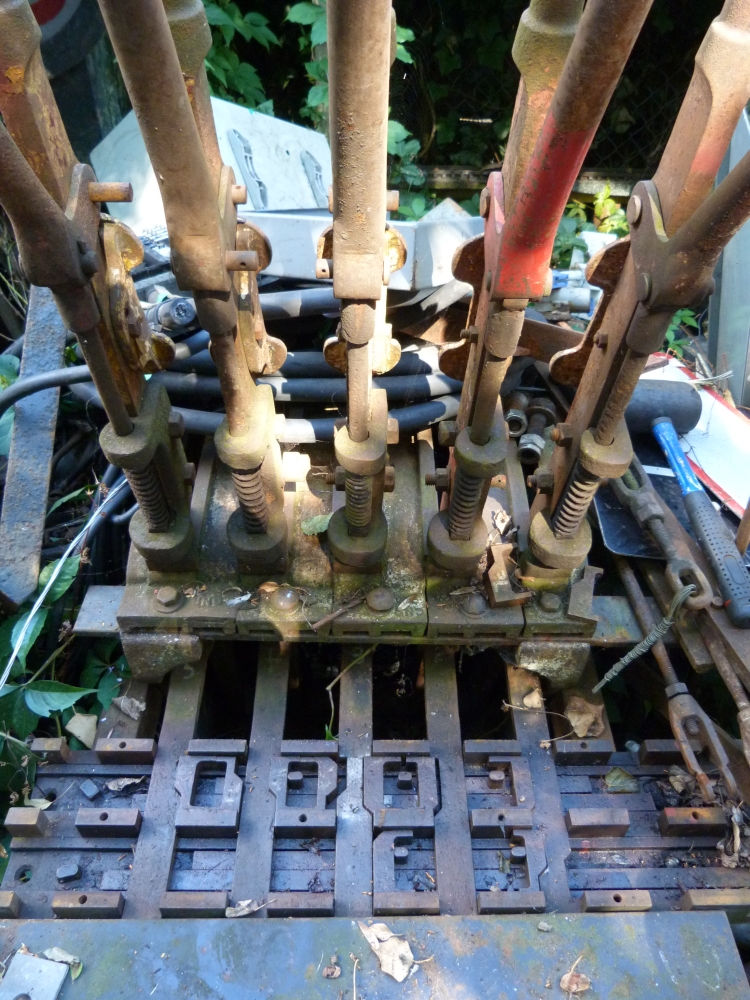
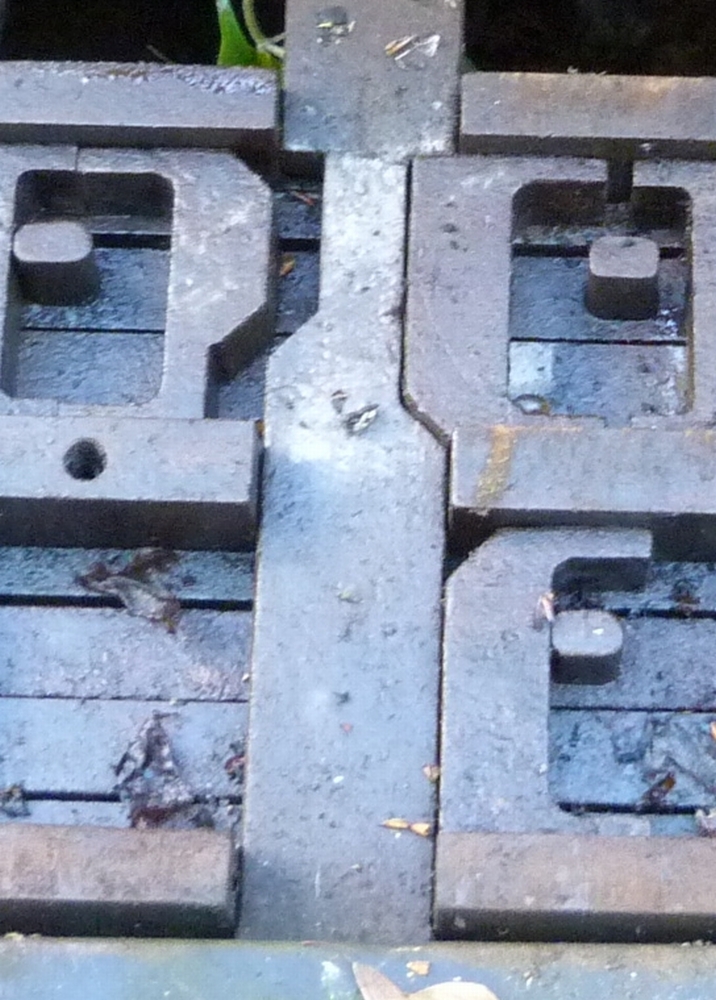
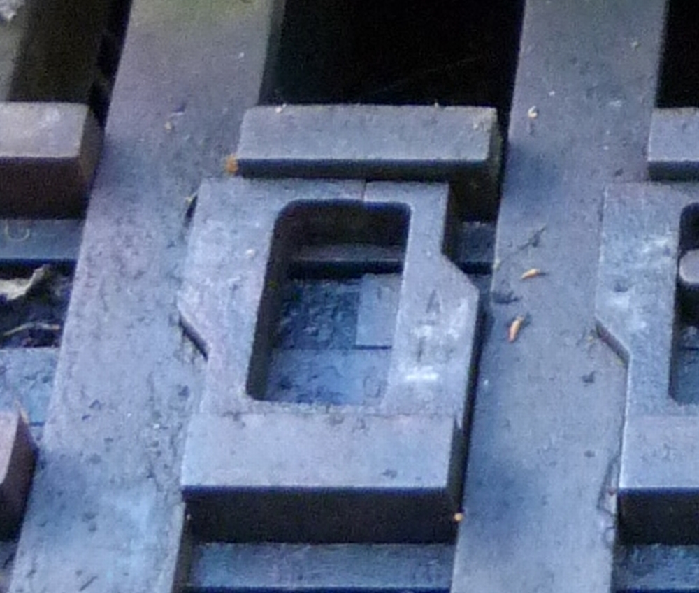
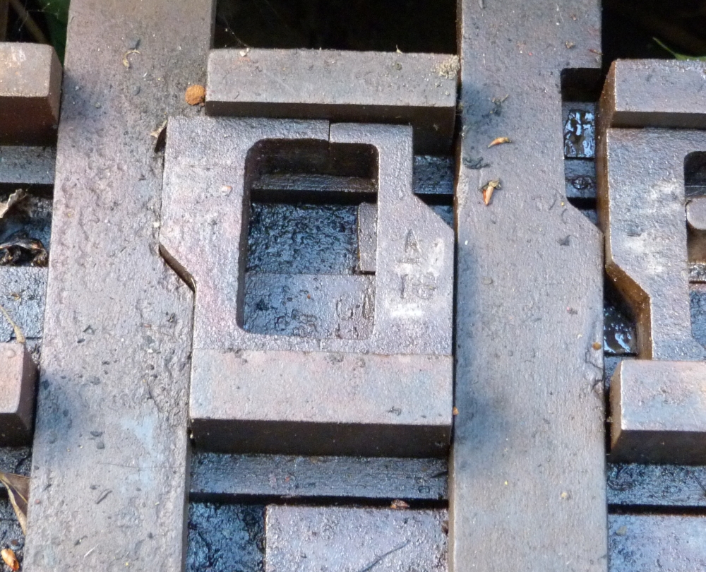
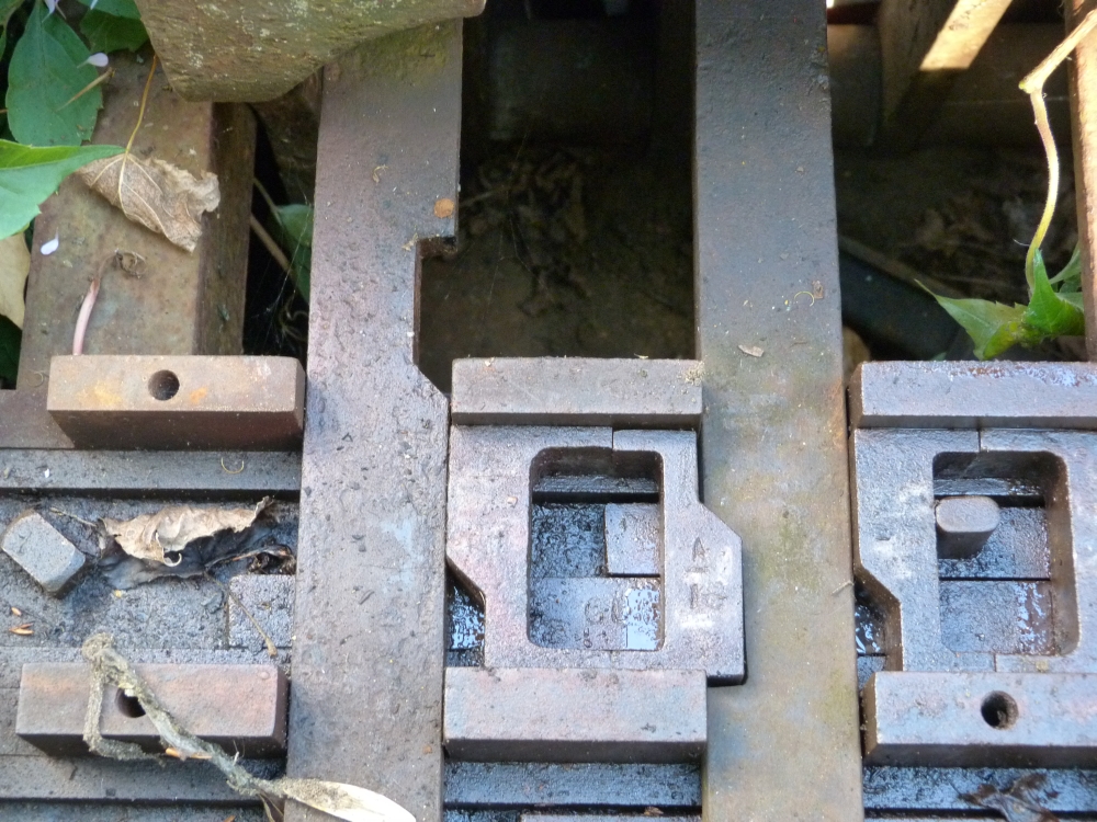
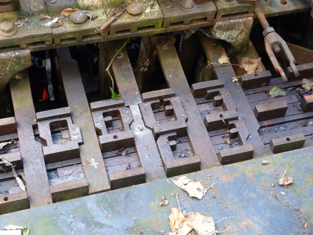
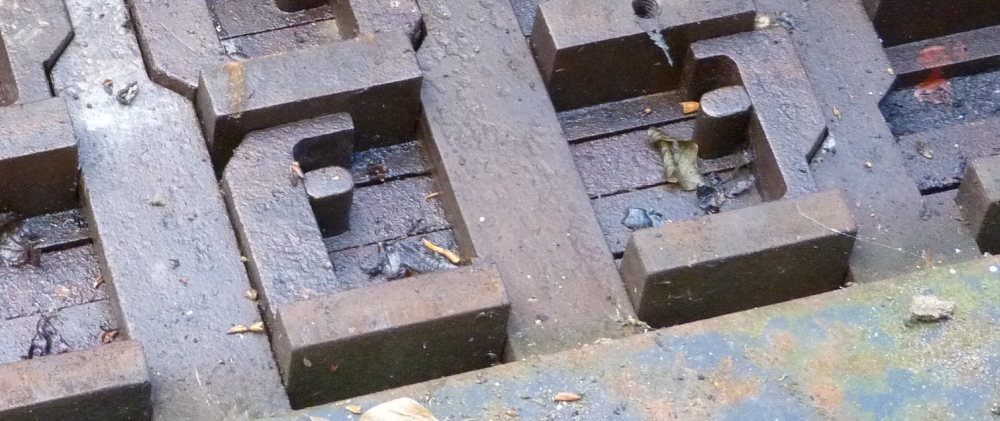
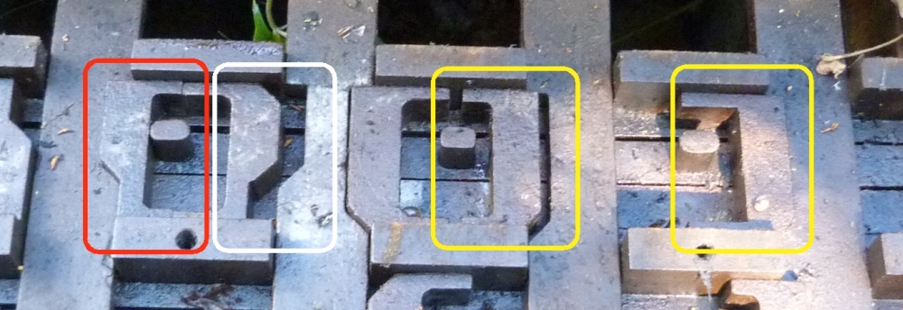
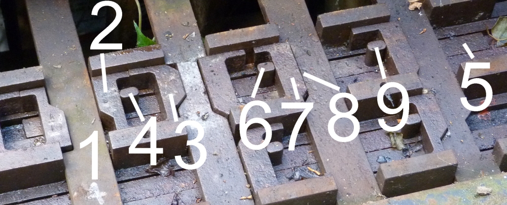
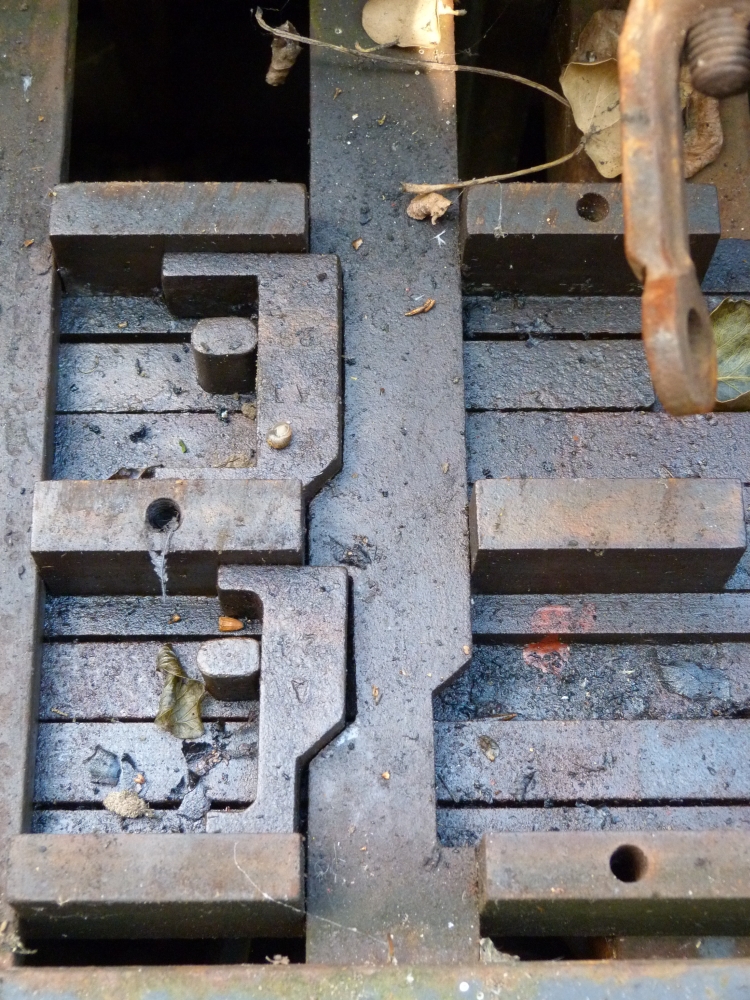
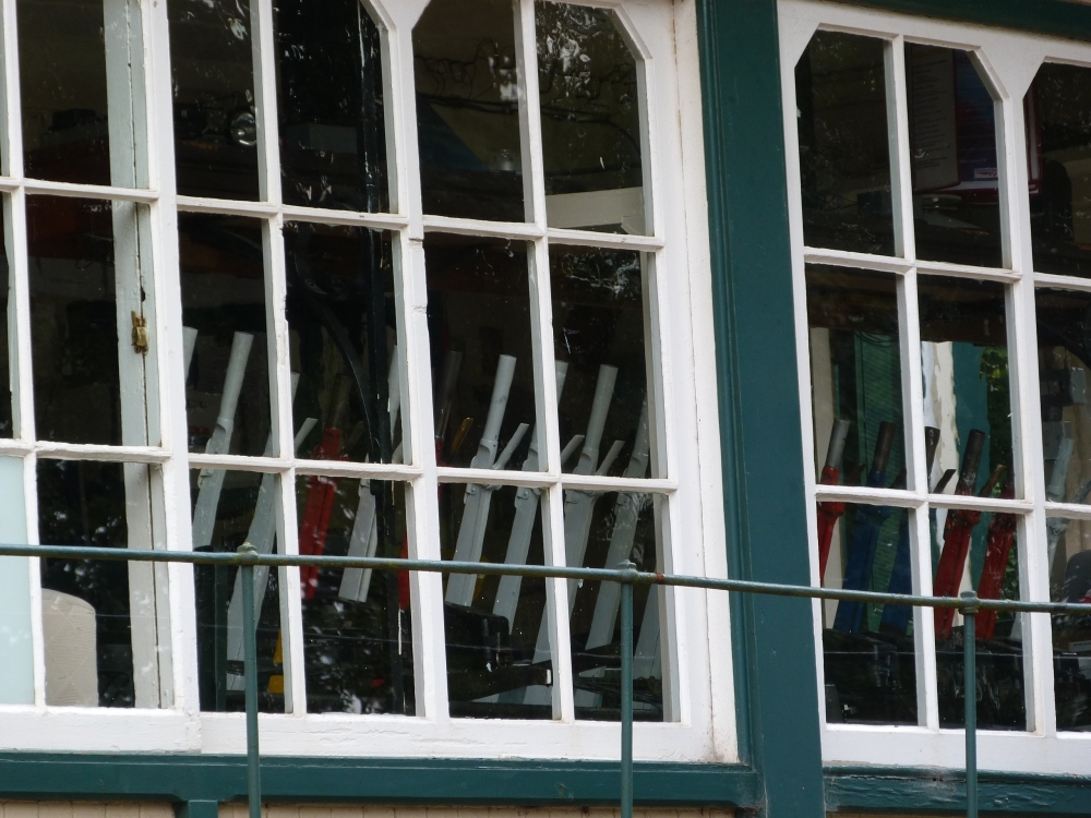
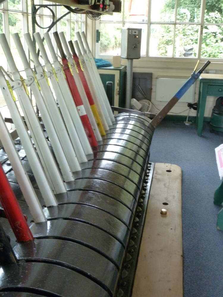
Some levers got original chains which move the contacts to control the model railway. These chains thus do not lead to any outside devices, but are "short-circuited":
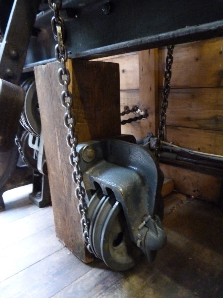
"Short-circuited" points chain, 12SA-frame "Steyrling", Sammlung Grafenberg, 16.4.2014
Here is a photo of one of the model railway's locos—more of them can be seen in some of the videos and on Werner's homepage:
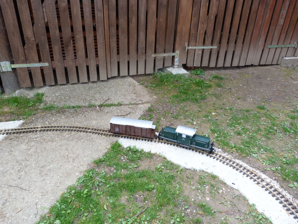
Model railway, Sammlung Grafenberg, 16.4.2014
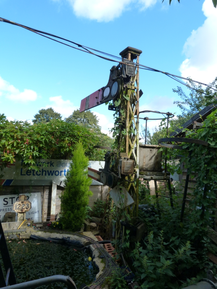
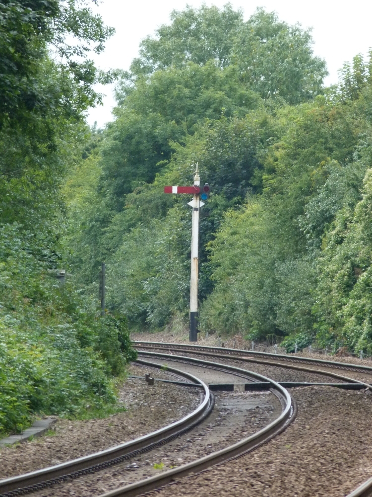
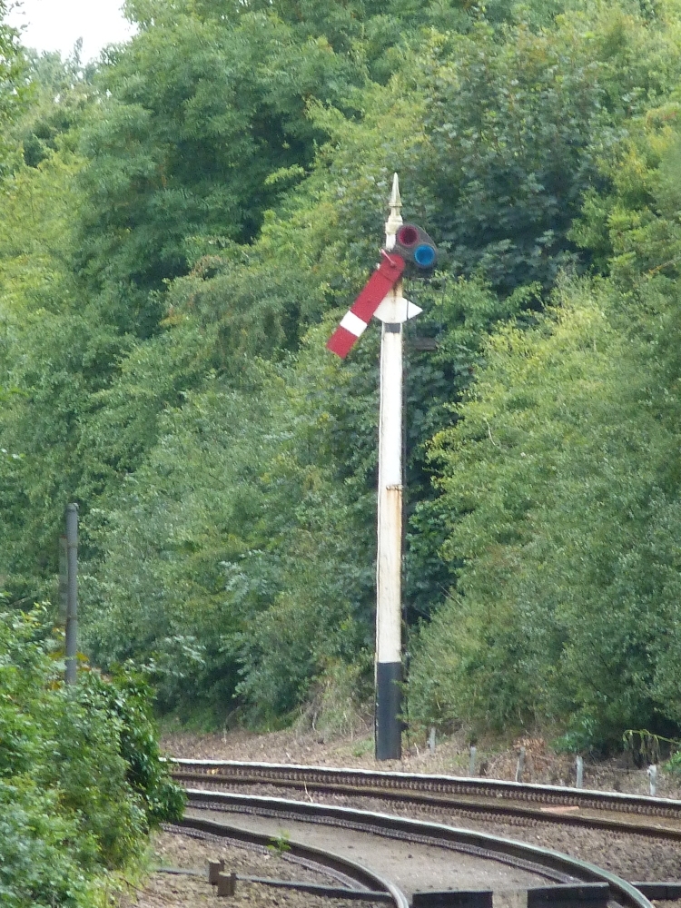
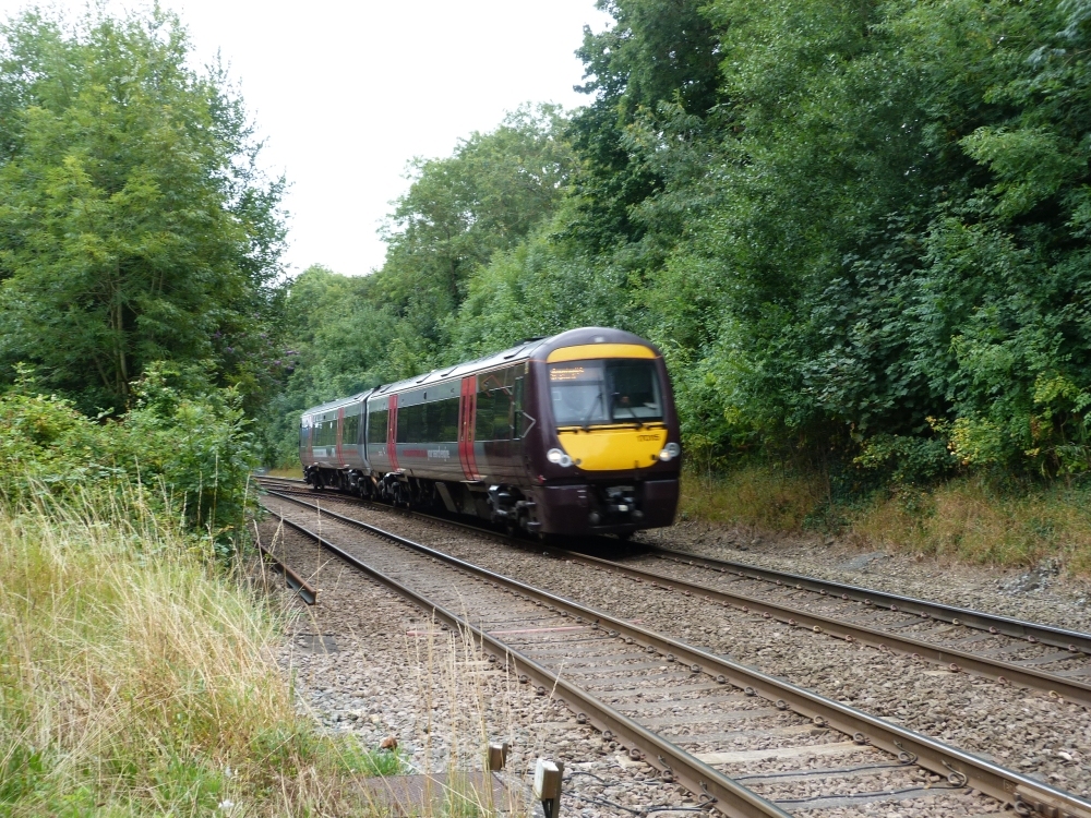
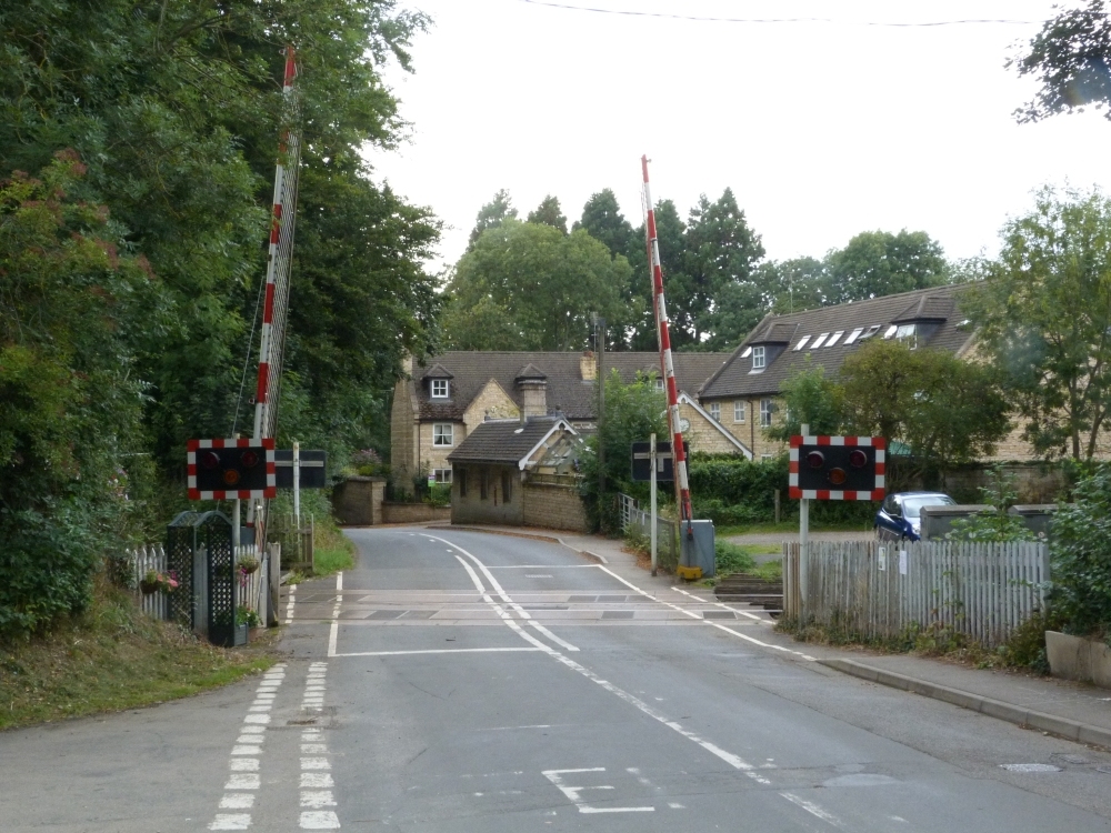
This is a shot of the old home signal A of Hetzmannsdorf-Wullersdorf, which is now used as home signal D of "Steyrling":
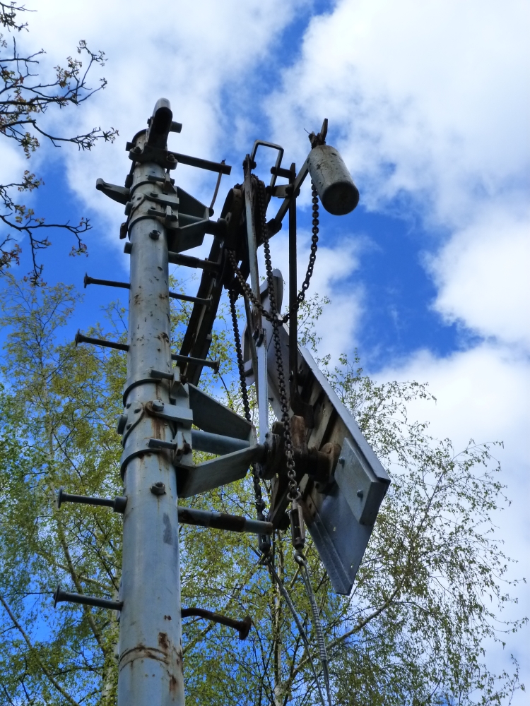
Home signal D of "Steyrling", Sammlung Grafenberg, 16.4.2014
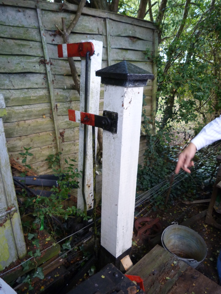
After we met, Werner has also installed a model semaphore as starter C, which has also been hooked up (electrically) to the 12SA frame:
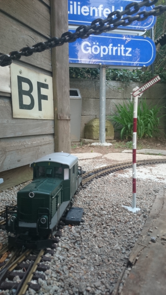
Starter C of "Steyrling", Sammlung Grafenberg, 23.4.2014
Besides "my" (but now Sammlung Grafenberg's) 12SA, one of the old lever frames that served at Absdorf-Hippersdorf has been moved to Grafenberg:
5007 frame "Absdorf", Sammlung Grafenberg, 16.4.2014
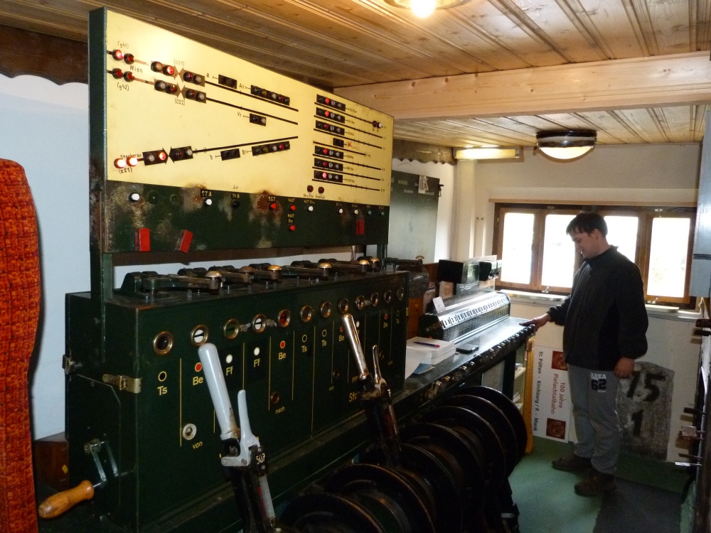
5007 frame "Absdorf", Sammlung Grafenberg, 16.4.2014
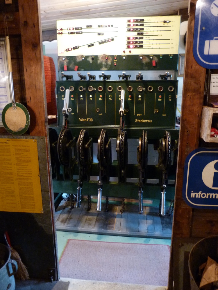
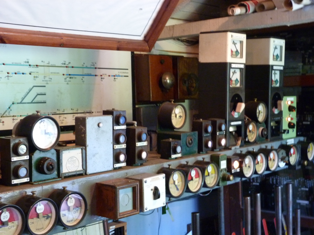
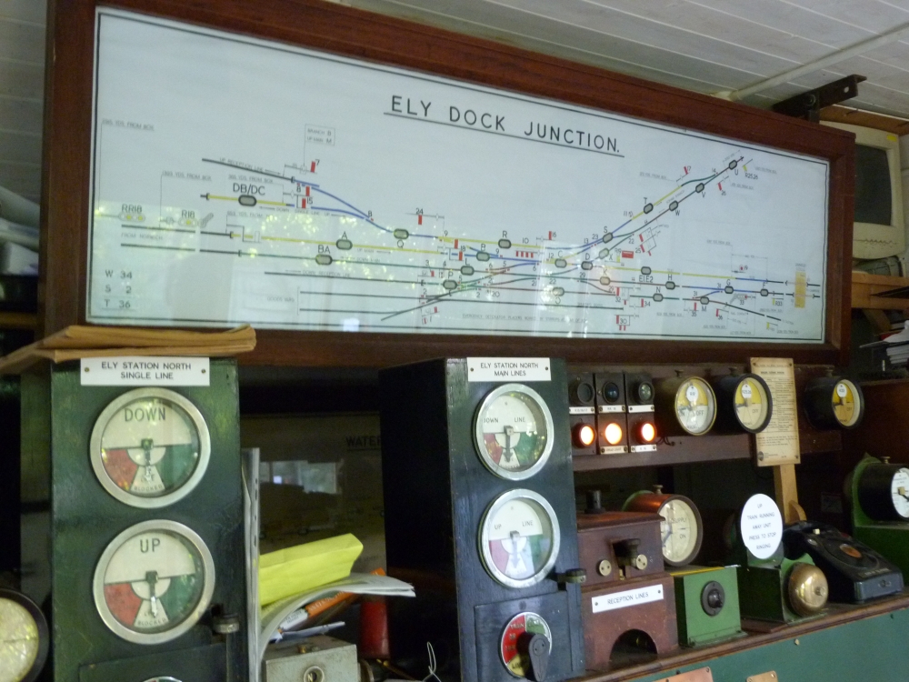
Frame and block instruments, 5007 frame "Absdorf", Sammlung Grafenberg, 16.4.2014
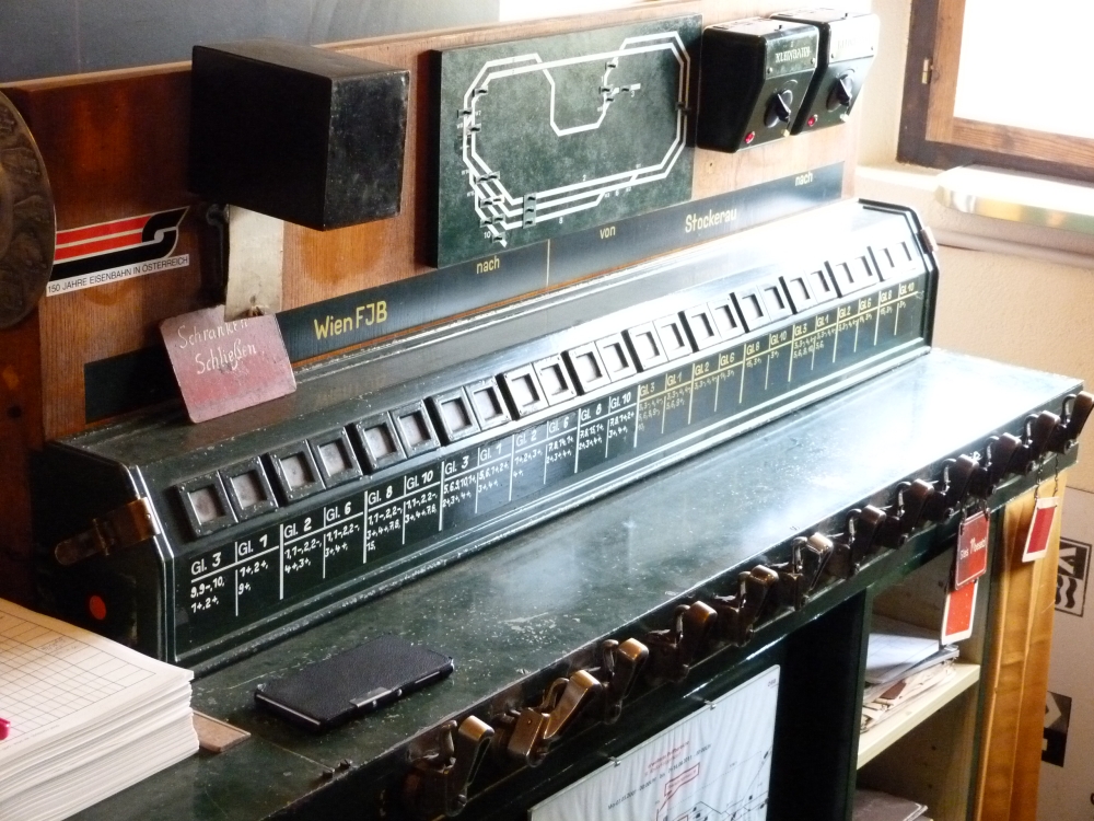
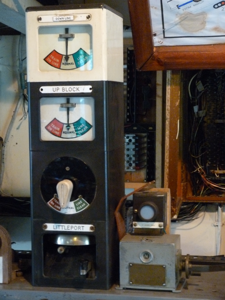
Track indiciator, 5007-Stellwerk "Absdorf", Sammlung Grafenberg, 16.4.2014
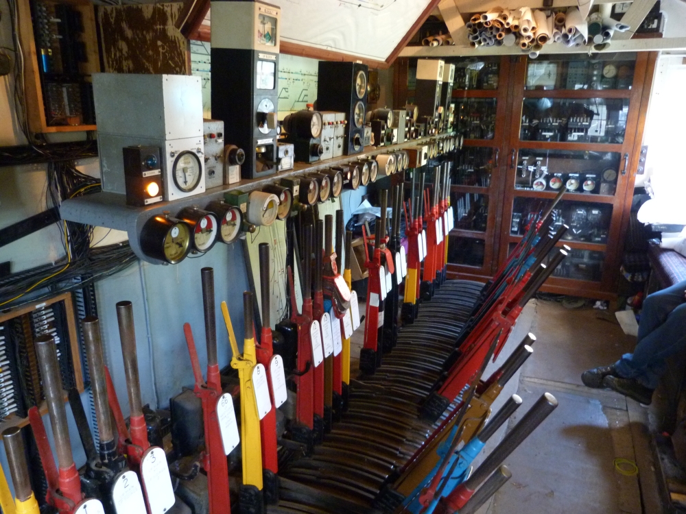
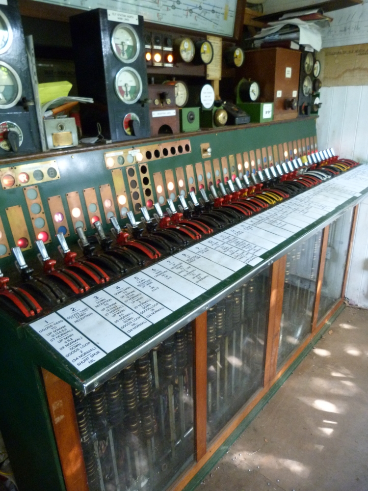
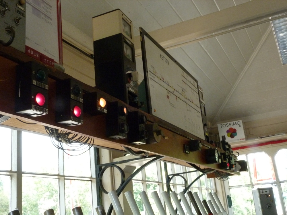
But now finally for a few impressions from our train runs. Here is my work place at "Steyrling":
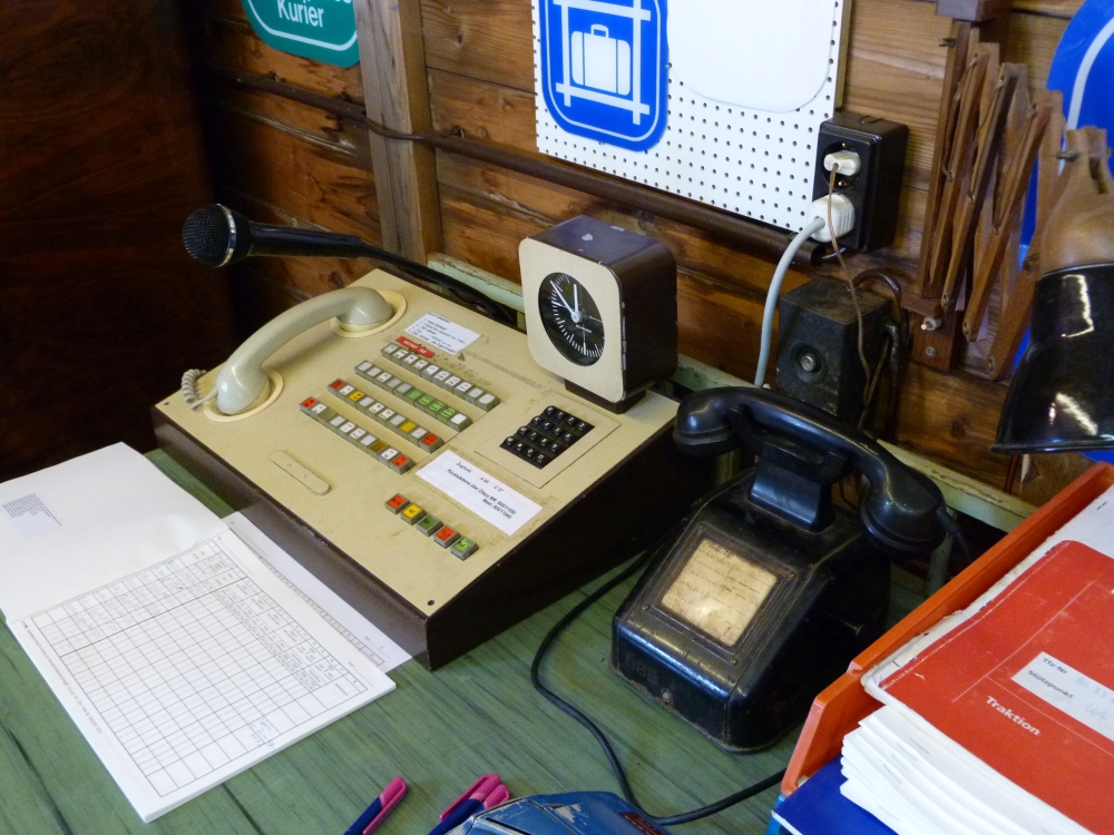
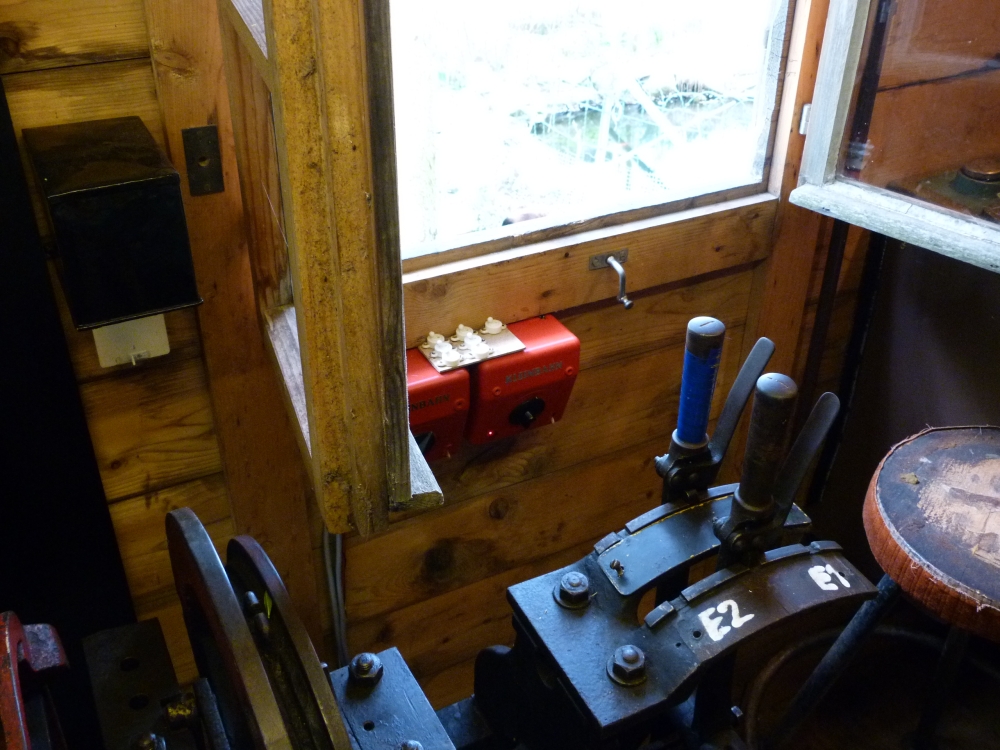
Traffic director's (signalman's) workplace at "Steyrling", Sammlung Grafenberg, 16.4.2014
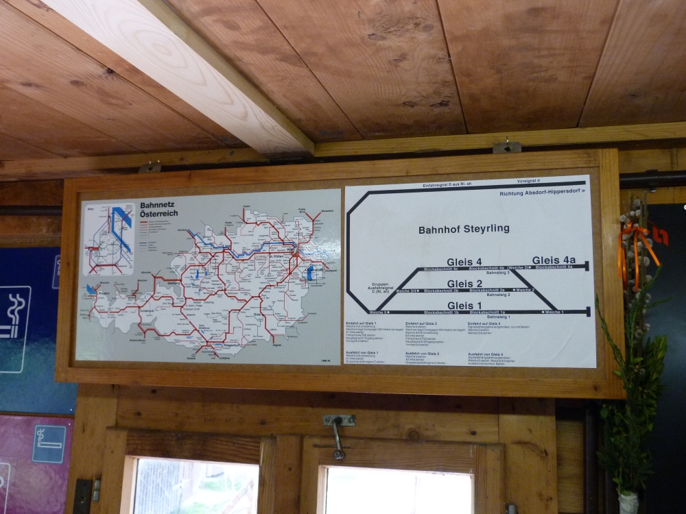
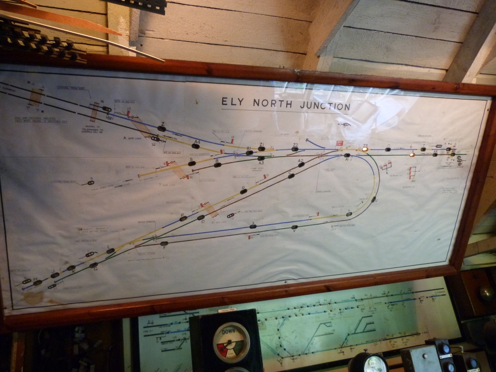
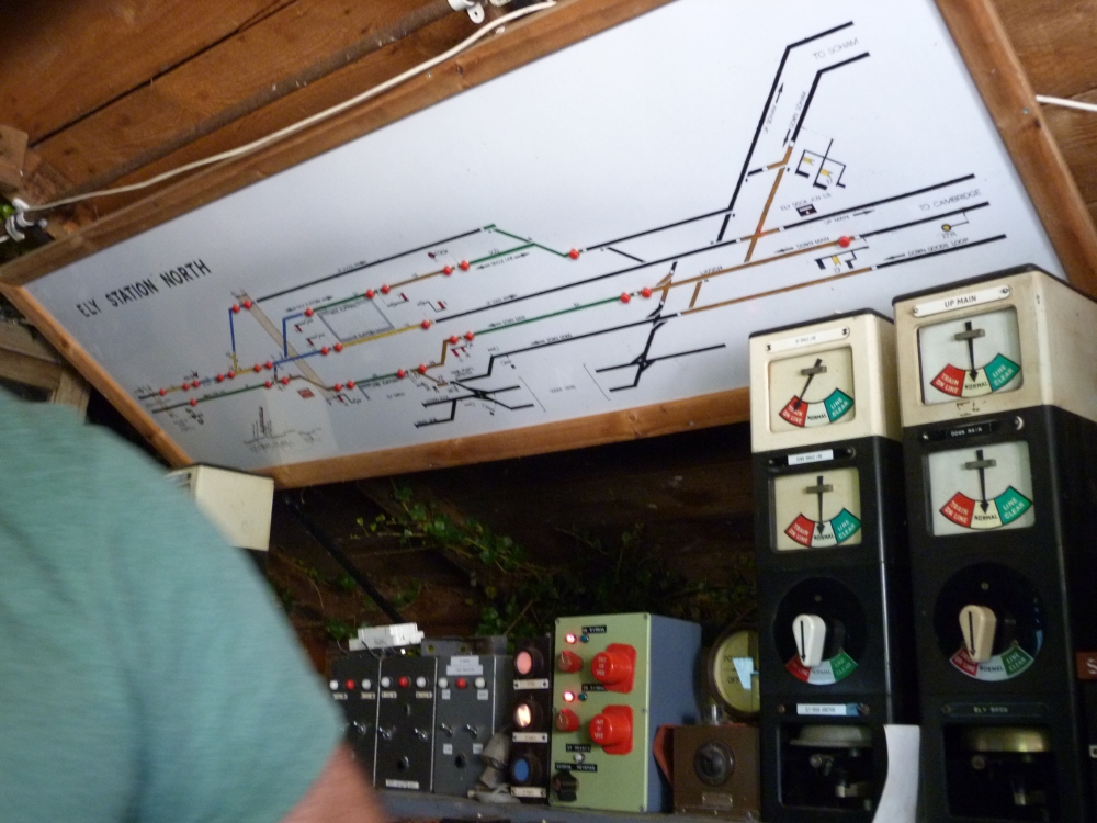
Track plan and instructions for handling of the 12SA frame at "Steyrling", Sammlung Grafenberg, 16.4.2014
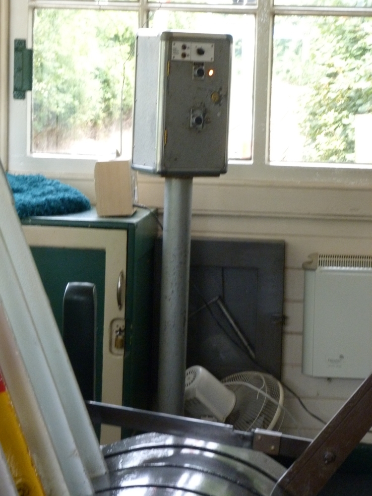
Model railway transformers and track switches for "Steyrling", Sammlung Grafenberg, 16.4.2014
And now for some action: The first train is announced:
Here it is:
A contact drops the warning bell, and then there's some work to do:
Actually, I was a little late, as can be seen here. It took me some time to get used to the controls of the various track supplies, and the track at that day still had a small kink with consequences:
Still, the signal must be returned:
A little later, I had announced my train to "Absdorf"—however, I had forgotten to turn the engine on the its side. Ok—more work:
But Werner used the time slot to send me a light engine which should fetch a wagon from the loading track at "Steyrling" (there's a photo of that train somewhere above):
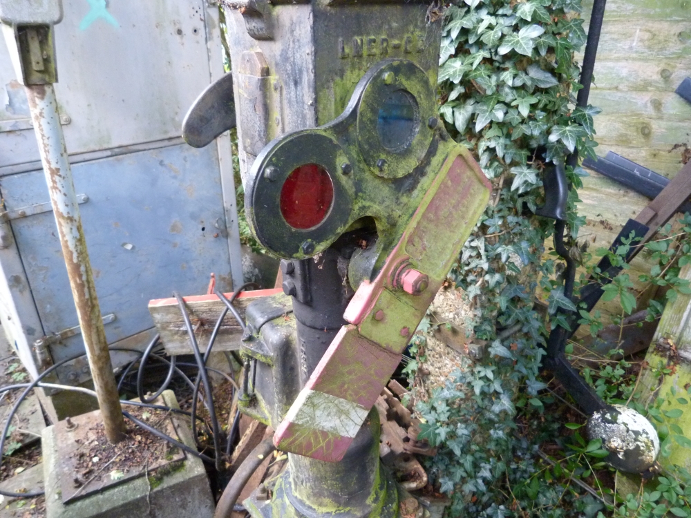
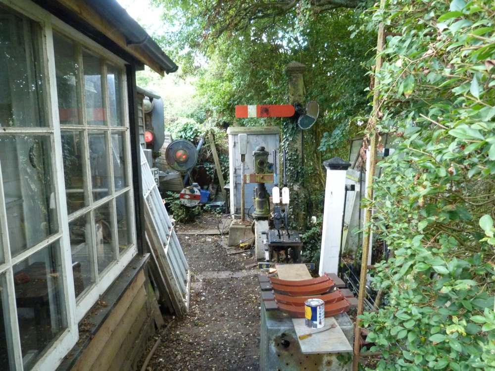
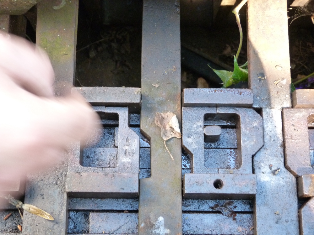
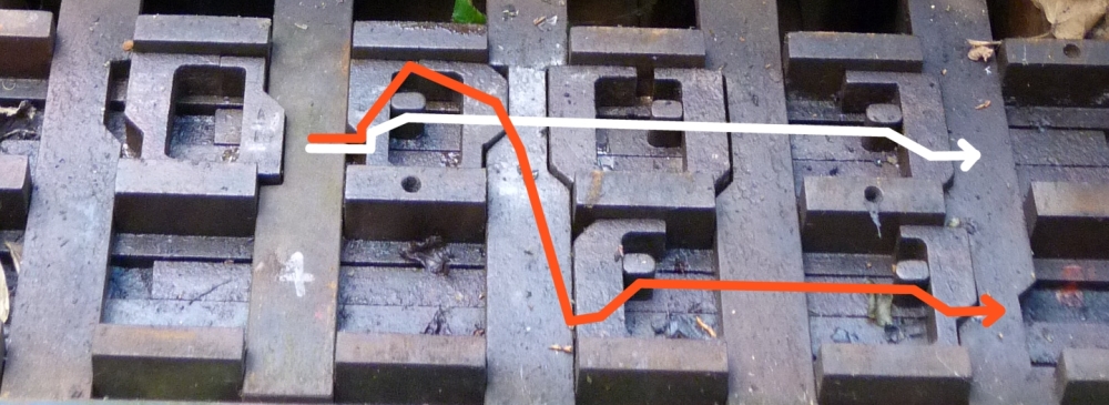
The two metal bars that can be seen here are necessary to reduce the wire travel for the semaphore from the signal lever's 500mm to the signal's 250mm. We took the raw design of this device from the Slovenian Railways, where old Austrian "Drahtnachzughebel" (wire pulling levers like this one at Greifenburg-Weißensee; the weights only have a function when one of the wires breaks) had been replaced with the simpler version at some places (an example can be seen in this posting in an Austrian railway forum). Our design is simpler than the original one and also matches the heights of chains and wires for the signal better. Unfortunately, there was still that kink in the track ...
... but it has been since repaired, tells me Werner!
And here, finally, the two track lists we filled out during our "game of trains". At least, we managed to end up with the same number of entries :-) ... but as I said before, I'll have to work a little at my knowledge of procedures!
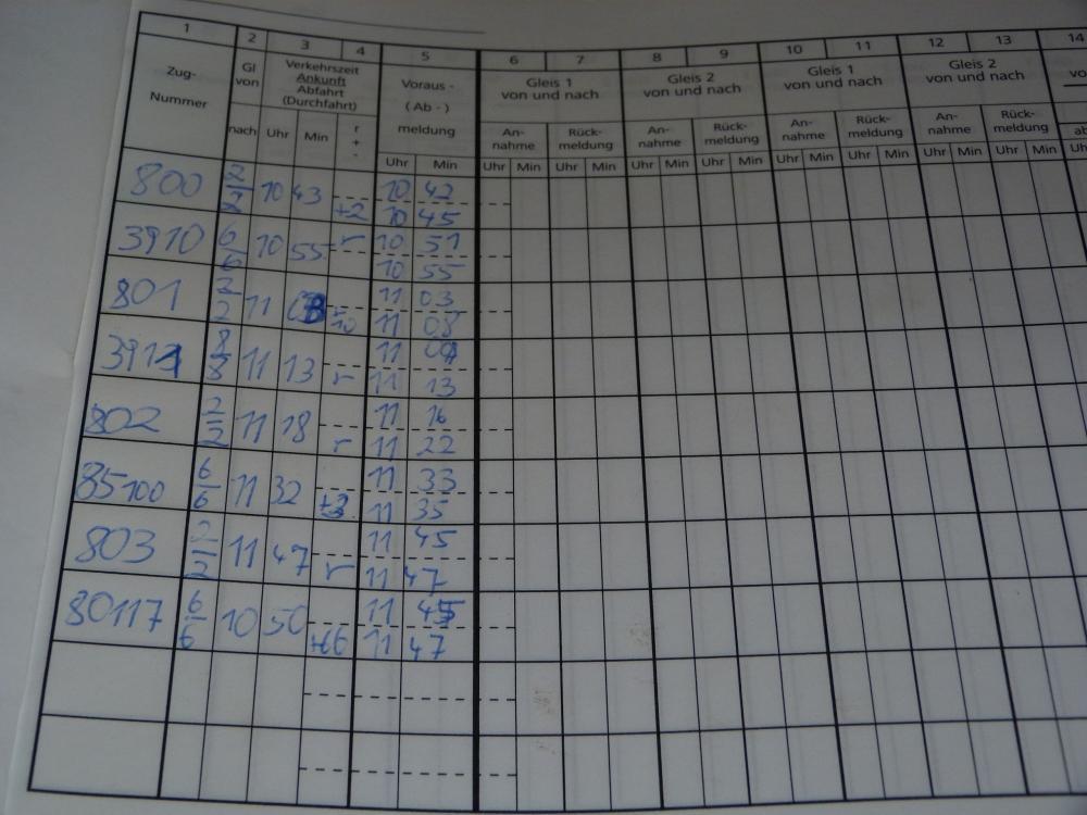
Train register "Absdorf" of our running day, Sammlung Grafenberg, 16.4.2014
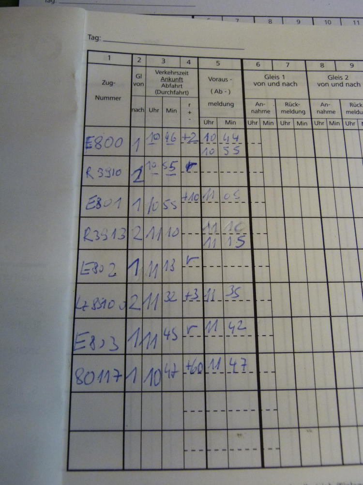
Train register "Steyrling" of our running day, Sammlung Grafenberg, 16.4.2014