A day before we left England, I got a short message from ... Richard Pike!—that "there were three more signal boxes nearby."
I wondered were they would be—no railway line there would still use old signal boxes. Then I found out: Two thirds of Richard's garden are sort of a signalling company's storage, with three fully working complex signal boxes, all connected to a relay simulator built from an old telephone exchange!
I made only a few pictures of the lever frames, as I had too much to ask and listen to during my visit. However, farther below are a number of photos from the locking bed of the tappet frame which (if I remember correctly) was brought to life again by Richard—I'll use them to explain a little bit more about tappet locking!
But let me start with some shots of Richard's working frames.
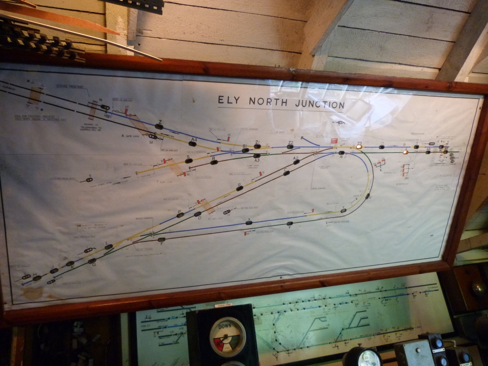
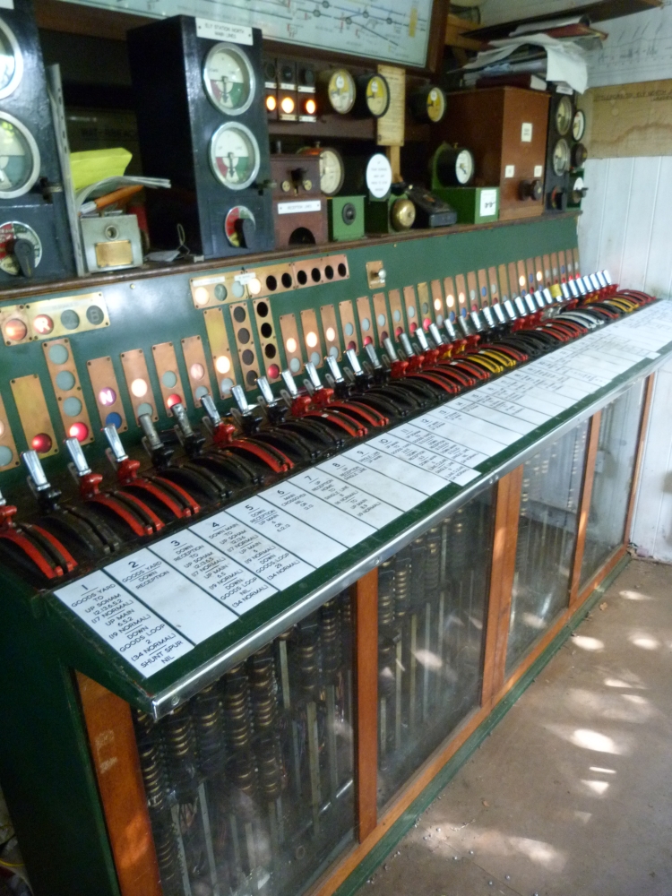
First, there is the mechanical frame of Ely North Junction:
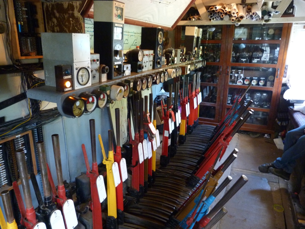
Ely North Junction frame at Richard Pike's, 30.8.2013
Ely North Junction frame at Richard Pike's, 30.8.2013
Ely North Junction frame at Richard Pike's, 30.8.2013
Ely North Junction frame at Richard Pike's, 30.8.2013
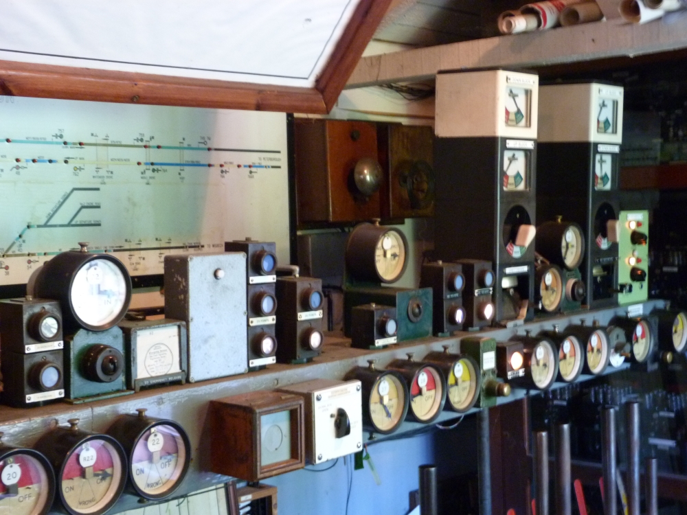
Then, there is the electro-mechanical frame of Ely Dock Junction:
Ely Dock Junction frame at Richard Pike's, 30.8.2013
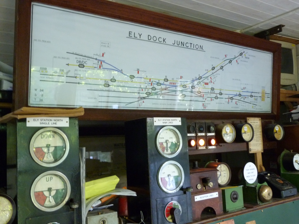
Ely Dock Junction frame at Richard Pike's, 30.8.2013
And finally ... unfortunately and for no reason I can remember, I did not take a picture of the third mechanical frame. However, part of Richard made it on the following shot:
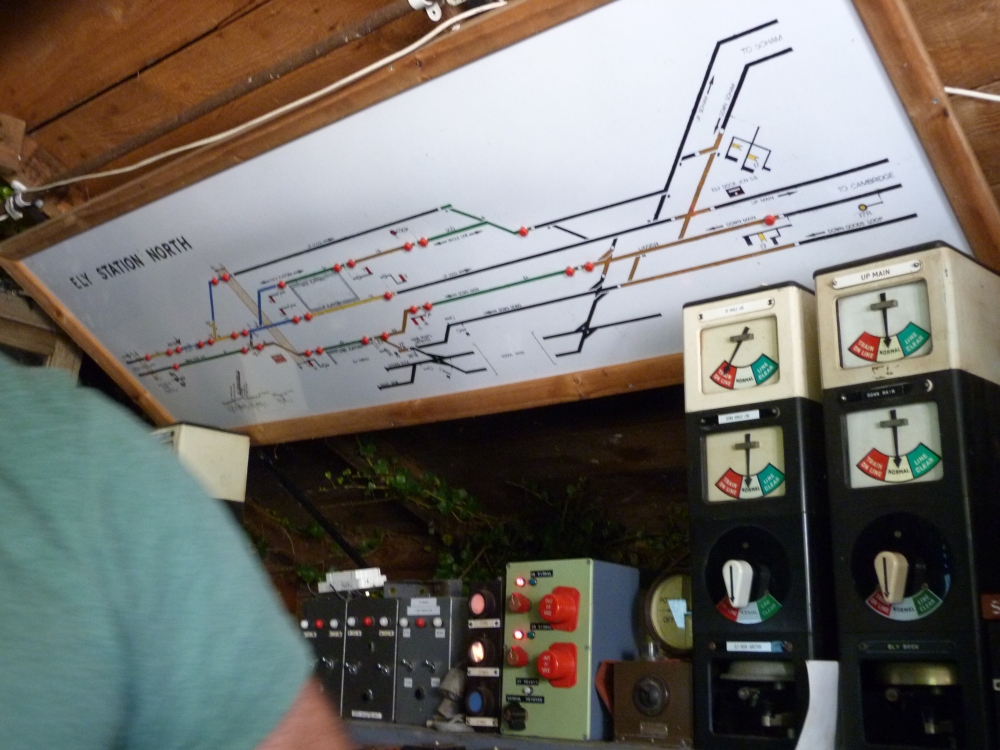
Ely Station North frame at Richard Pike's, 30.8.2013
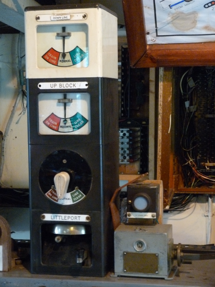
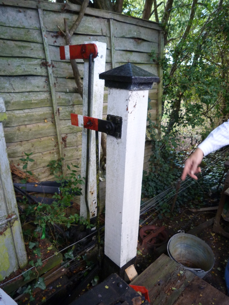
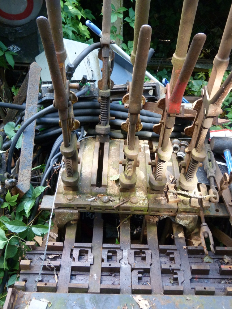
Outside, Richard has got quite a number of signalling equipment:
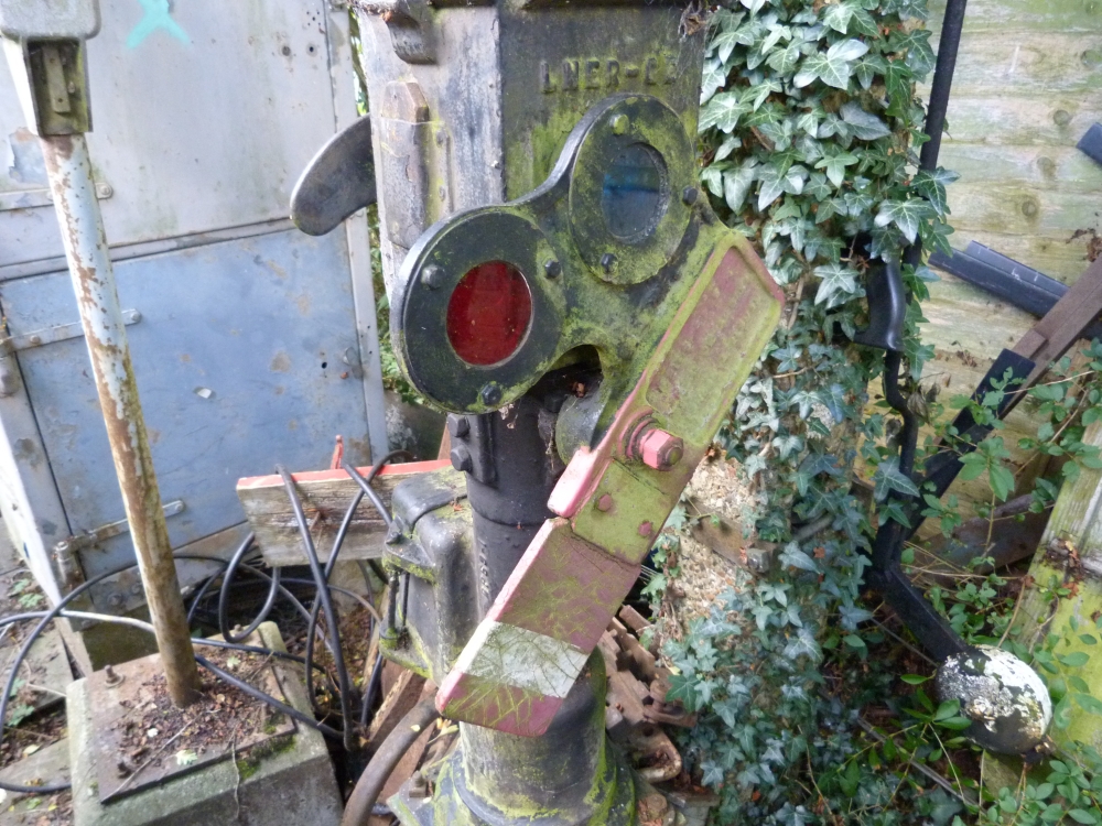
Shunt signal partly made of rubber (to reduce the risk of injury) at Richard Pike's, 30.8.2013
30.8.2013
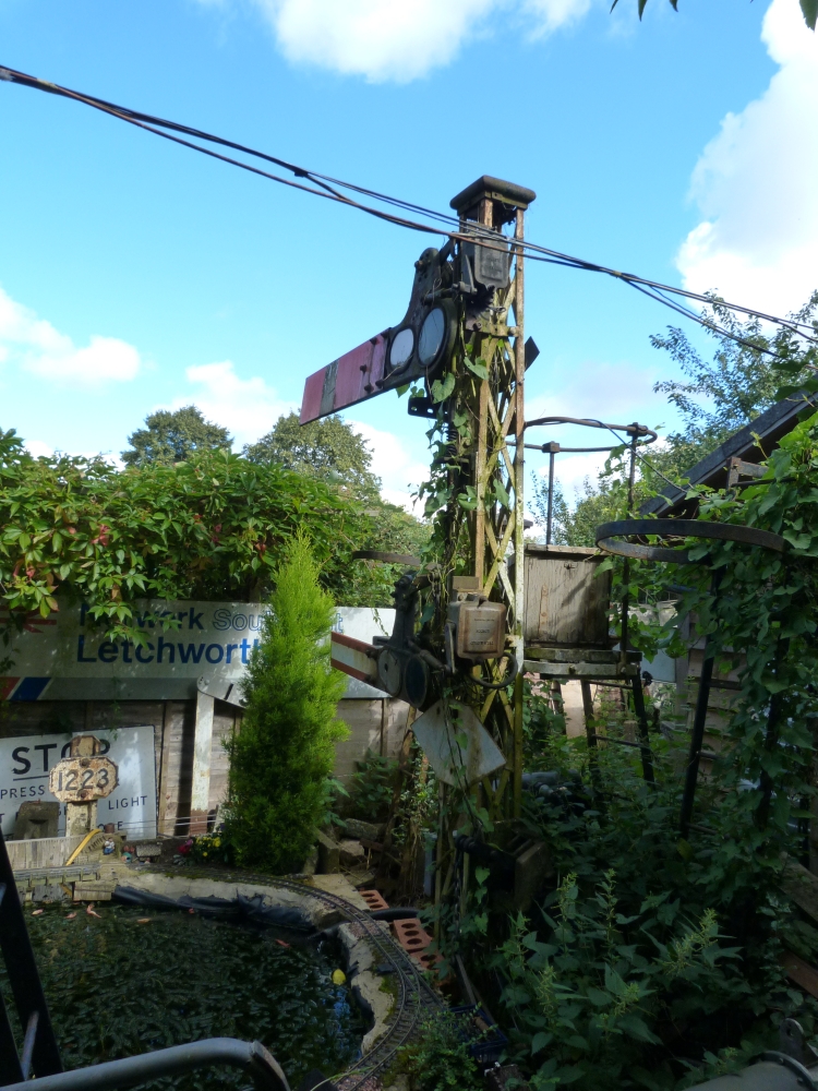
30.8.2013
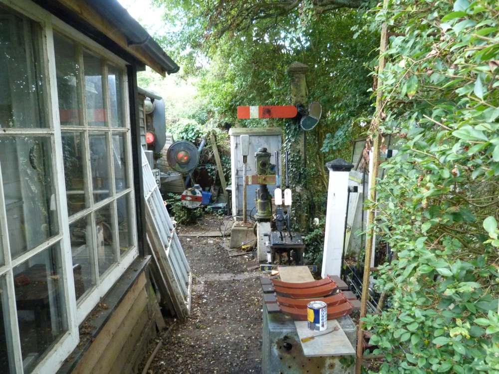
Richard was, as remarked above, preparing a small ground frame. A few parts with fresh brown paint were drying:
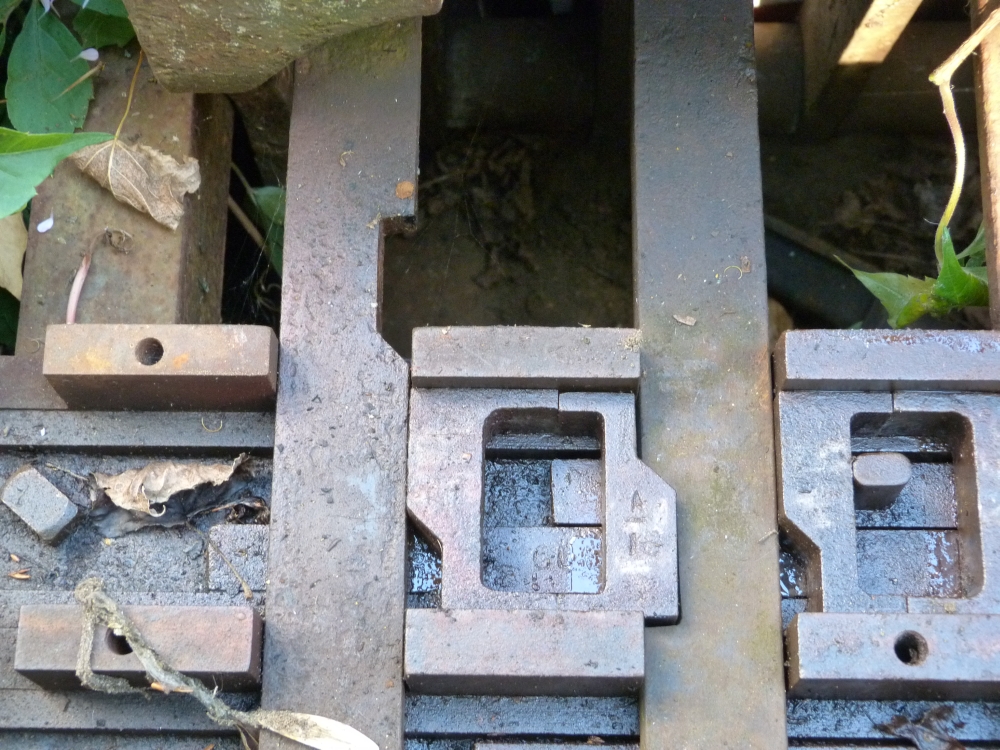
And here are the final signalling-related pictures from our vacation in England, explaining the typical parts of a tappet frame. The frame is shown here from the back side, and the locking bed has already been opened. Some tools and some—well—other things are lying near and on the frame—so it goes ...
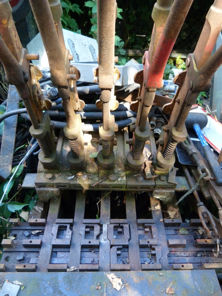
Here is a closer look at the locking bed. It is a quite simple locking bed—there are much trickier ones. However, it shows a number of typical patterns how levers lock each other which I'll shortly explain:
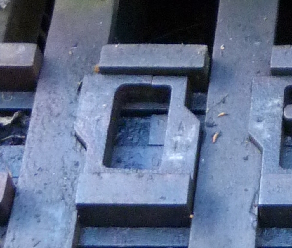
At first, we look at two neighbouring levers that lock each other like the ones in the ground frame at Wansford. Here, one can see the two tappets, with a pair of wedges between them. The left lever is locked in this situation—can you see why?
Here is the explanation:
- In order to reverse the left lever, its tappet (the flat iron) would have to move (towards the top of the picture).
- This would force the left wedge to the right, via the short tapered edge.
- But this would also have to move the right half of the wedge pair (as the wedges touch each other at the top and the bottom), ...
- ... which is impossible as there is no cut corresponding to the wedge in the right tappet!
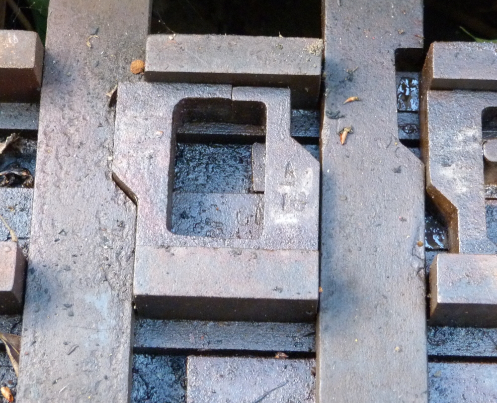
How can the left lever be unlocked? For that, the right lever must be reversed. Here we see the first fraction of it smovement—the cut on the right has moved (up, in the picture) a little bit (thereby, the wedge on the right wide has been pushed out—but we'll ignore this for the moment). The left lever, by the arguments above, is still locked:
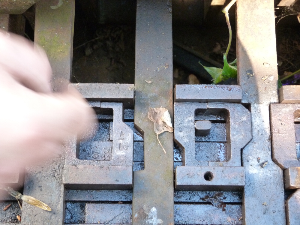
When the right lever has been completely reversed, a cut in its tappet is now positioned opposite the wedge. This, of course, finally allows the wedge to move to the right if pushed by something! (Sorry for the hand in the photo ... it's probably mine, but I don't know why it's there ...):
And now the left lever can be moved! Here we see that its tappet has already been pulled (again upwards, in the picture) by its lever. The taper at the cut has forced the left half of the wedge pair to the right, which in turn has pushed the right half into the matching cut of the tappet of the right lever—which, therefore, is now itself locked into its place!
If the leftmost lever is moved back, the cut in its tappet will of course again be aligned with the wedge—but the wedge will remain outside the cut until the movement of another lever forces it back. Here is the situation after the first lever was moved back:
Four pictures up, you can see the situation where the wedge has been forced back into the cut in the left lever's tappet.
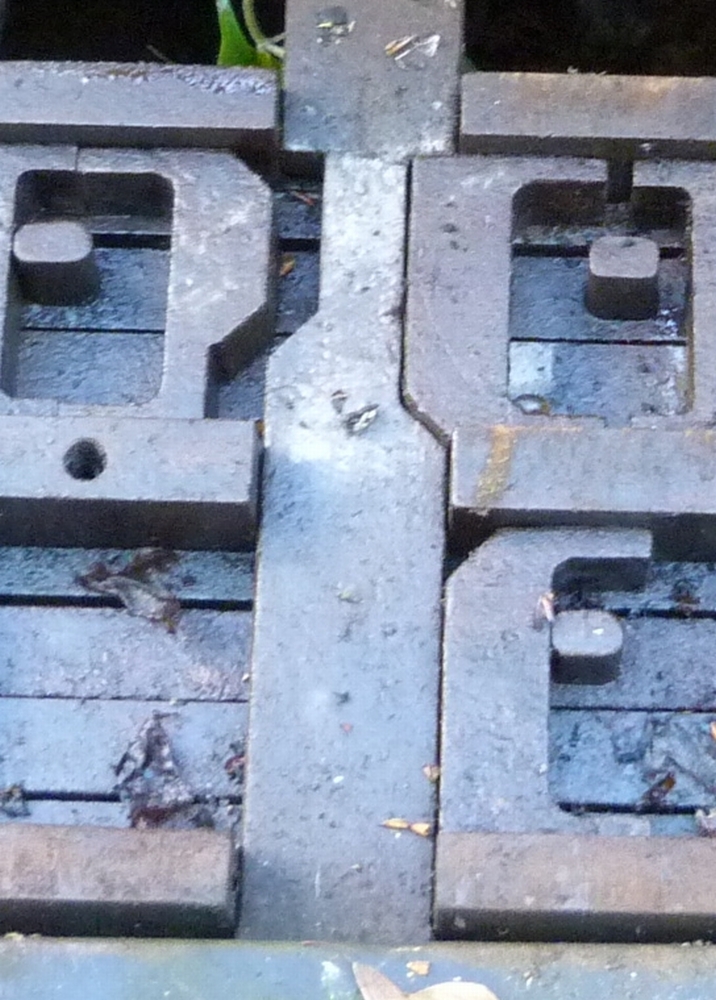
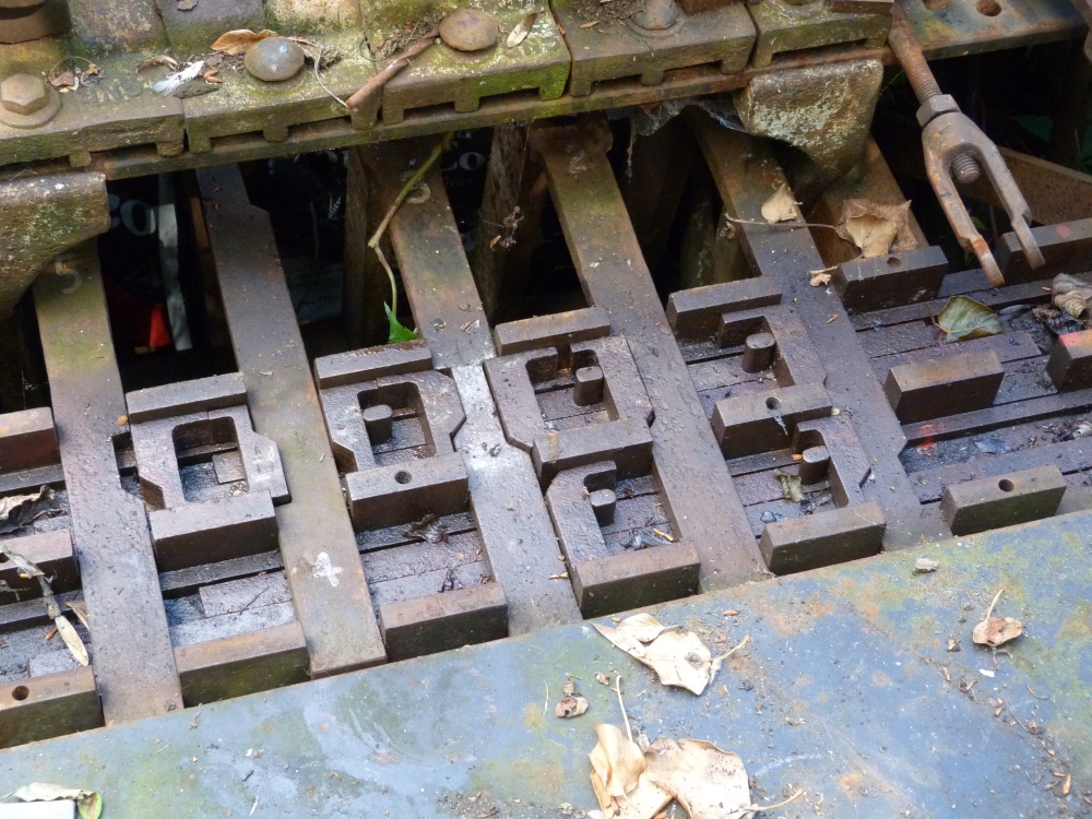
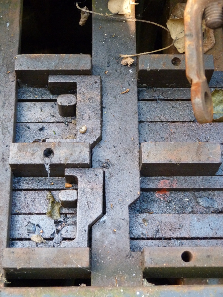
Up to now, we have only dealt with neighbouring levers. However, in many cases it is necessary to lock levers that are not neighbours of each other. This is where connecting rods become necessary. The next picture shows a simple example: There are three levers—left, middle, and right. The left lever should be locked against the right one, with no locking logic for the middle. The solution is easy:
- The two wedges are placed against the corresponding tappets.
- Below them, a connecting rod is placed with two noses that push the wedges.
One can see that two noses project from the connecting rod that push or are pushed by the wedges. However, the connecting rod is not centered, but somewhat offset. This makes room for another connection rod which can connect other wedges in the frame. In the locking bed shown here, the trough where the connecting rods run can contain two connecting rods; in other designs three or even five rods could be placed in one trough. But of course, more than one trough might be necessary:
- Either because more connection rods are necessary than would fit into one trough;
- or because a tappet has to be locked with more than two wedges (only two wedges per tappet per trough are possible, one on each side).
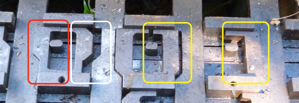
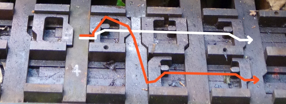
Of course, a single lever can lock more than one other lever. Typical examples of this are signal levers which lock all the points levers (or the facing point lock levers) that are guarded by the signal. In this frame, there is an example where a single lever locks three other levers: If the leftmost tappet in this frame is moved, its wedge (marked red)
- ... will directly push over the wedge marked white;
- ... will push the connecting rod with the nose seen in the red area, which in turn ...
- ... will push (with two more noses) two wedges against the tappets of the remaining two levers in the picture.
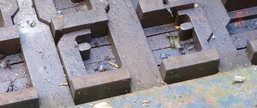
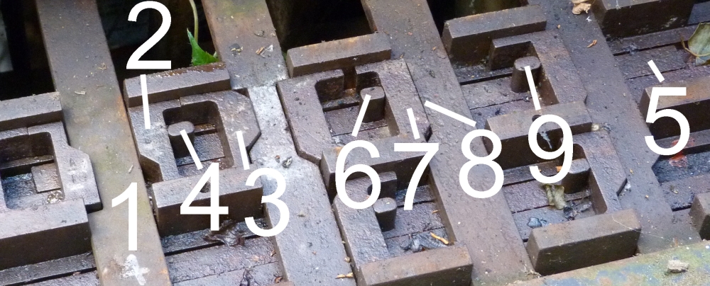
The next picture shows the situation when the lever has been reversed:
- The tappet (1) ...
- ... has forced the wedge (2) ...
- ... to the right, so that it pushes (with the protrusions at its top and bottom) the next wedge (3) into the neighbouring tappet's cut and locks it into place.
- Moreover, the wedge (2) pushes the nose (4) to the right, which shifts the connecting rod (5).
- With its nose (6), the connecting rode pushes the wedge (7) into the cut of the tappet (8), thereby locking this tappet.
- Also, the nose (9) shifts the wedge .......
The final pictures show that the rightmost lever is locked twice:
Here is picture of the full frame in this situation ...
... and here is a picture of the two dependency chains that start at one tappet and force wedges and connecting rods to the right so that the rightmost tappet is doubly locked:
This is by no means the high end of tappet locking—much more elaborate and even tricky locking beds are possible and necessary for large signal boxes. If you are interested in the intricacies of large interlockings, you might want to read pages 270 to 300 of Railway Signal Engineering (Mechanical), by Leonard P. Lewis, published in 1912. Be warned: It might take you a week or two if you want to understand each line of text.
And that's all from our 2013 "signal box" vacation in England!
No comments:
Post a Comment