As I promised, after the initial posting about mechanical interlockings in the Netherlands, I continue here with a sequence of photographs (and, hopefully, less text) about the signalling equipment at Wijlre-Gulpen. The next posting will, once again, try to highlight more conceptual aspects of Dutch mechanical interlocking.
The station tracks
In the following picture, which looks eastward, one can see the through track on the left and the loop track on the right. Near the loop track, the station building contains "post T," i.e., the train director's bureau:
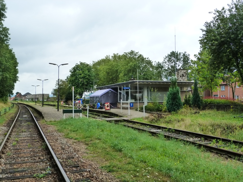
Station building, Wijlre-Gulpen, 16.8.2015
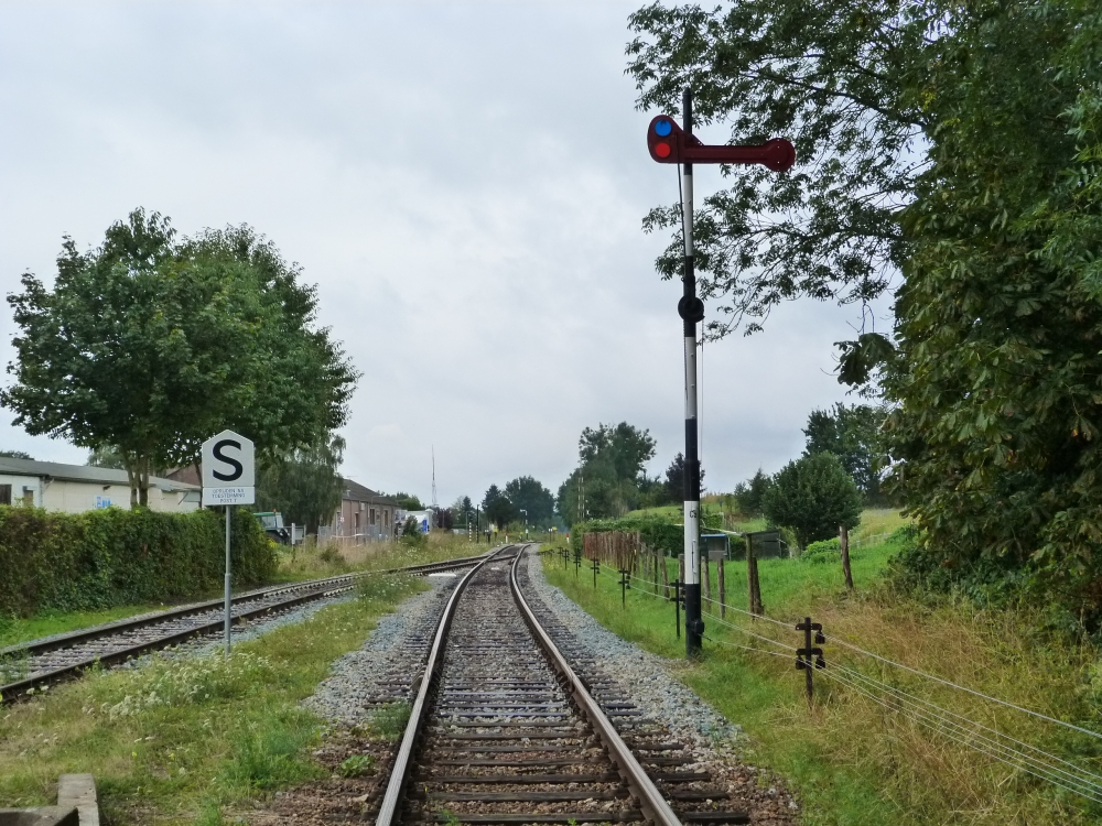
Turning around, one can see the western throat. The loop does not (yet) have a starter, only an "S bord" (stop board). Besides the through track, starter C2 secures the line towards Schin op Geul. Behind points no.32, a barrier-protected crossing can be seen:
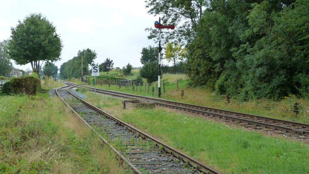
Station tracks towards Schin op Geul, Wijlre-Gulpen, 16.8.2015
Standing on the the crossing, one can see that there is an additional set of points into a stub track. In earlier times, the line to Schin op Geul was double tracked—these are the remnants of that second track. To the left of the line, one can see home signal D1 and, far away, the corresponding distant signal Dv:
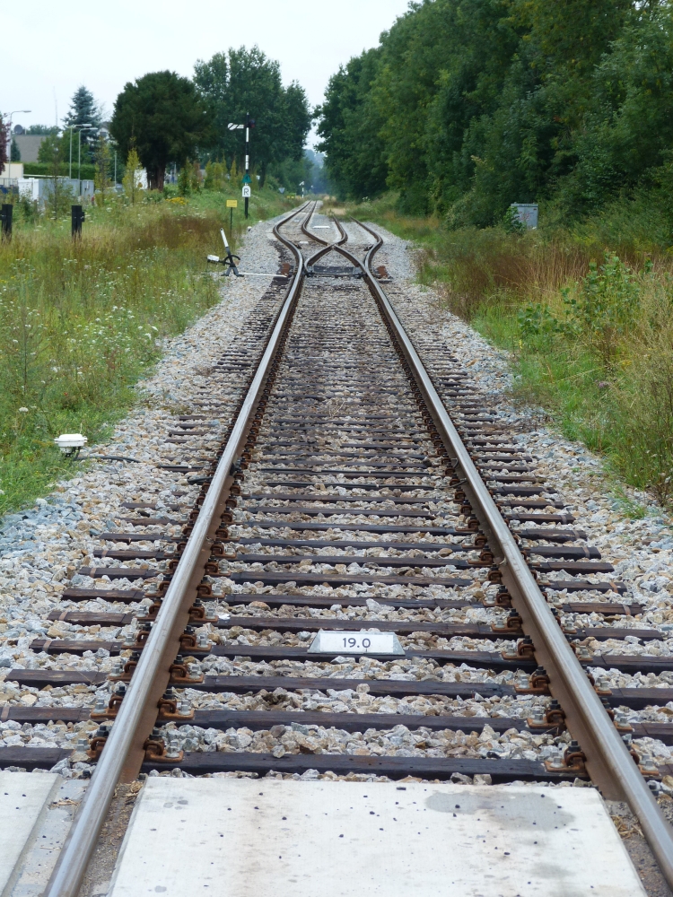
Points to stub track, Wijlre-Gulpen, 16.8.2015
Inside post T, this track plan shows the signals, points, buildings and crossings of the station—however, this plan does no longer match reality!
- The old trap points 302 are completely gone.
- Switch no.32, where the two line tracks joined up, is now behind the crossing and has some other number.
- Switch no.33 into the loop track is now no.32 and located inside the crossing.
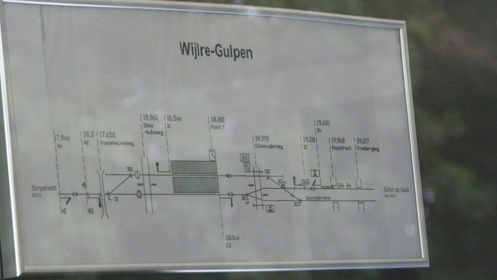
Track diagram, post T, Wijlre-Gulpen, 16.8.2015
This is post T. Behind the large glass panes, one can see the interlocking frame with its block instruments and the chains on the levers:
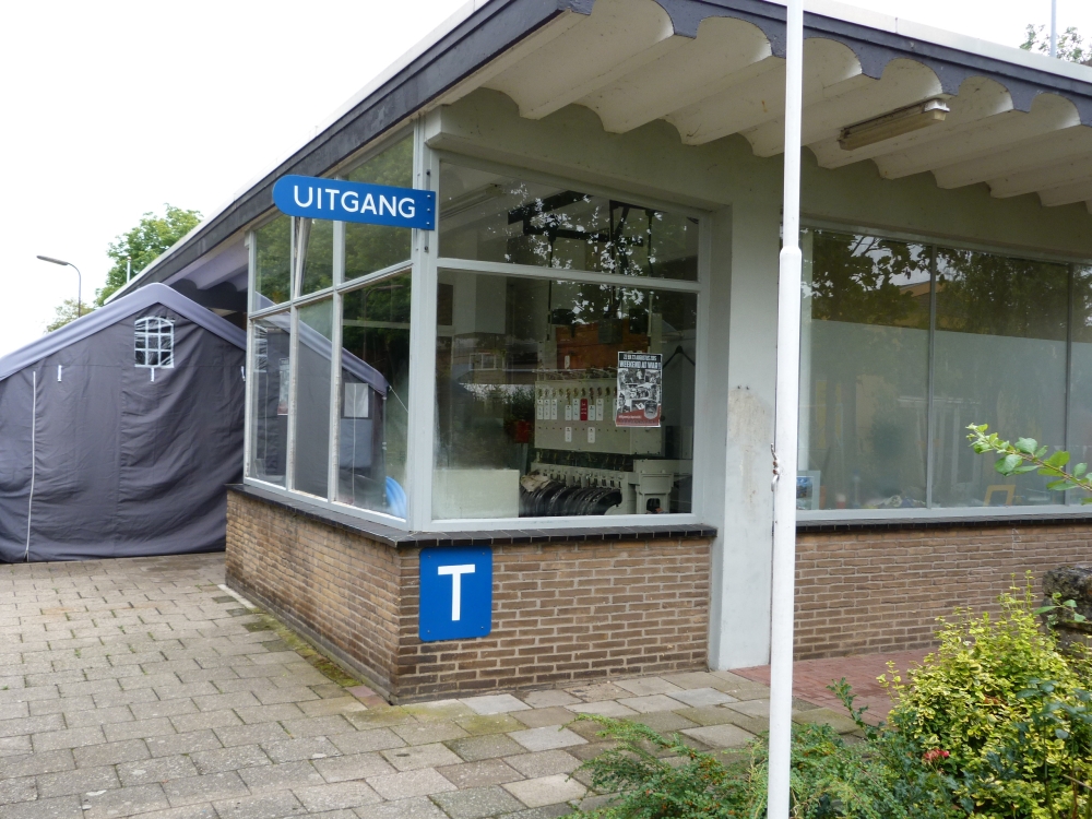
Post T, Wijlre-Gulpen, 16.8.2015
The tent on the left was installed for a fair taking place a week later, if I remember correctly:
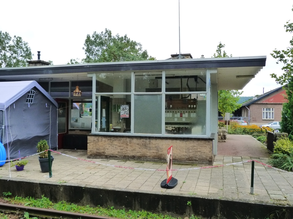
Post T, Wijlre-Gulpen, 16.8.2015
From this side, one can see the workplace of the "treindienstleider," i.e., the train director:
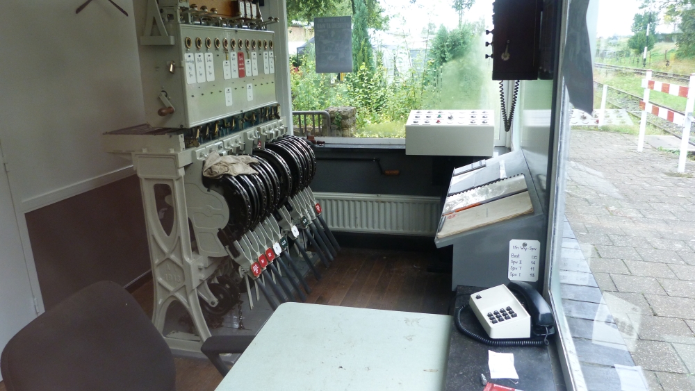
Interlocking frame and workplace, post T, Wijlre-Gulpen, 16.8.2015
In the next picture, one can see an interesting detail of Dutch interlocking frames: The case containing the block instruments is not mounted on top of the lever frame, rather it is suspended from brackets that run on short rails below the ceiling. This mounting allows a simple removal of the block instrument case when working on the route bars on top of the lever frame. Many such suspension brackets can be seen in the folder "Seinhuizen" (i.e., "signal boxes") on klassiekebeveiliging.com:
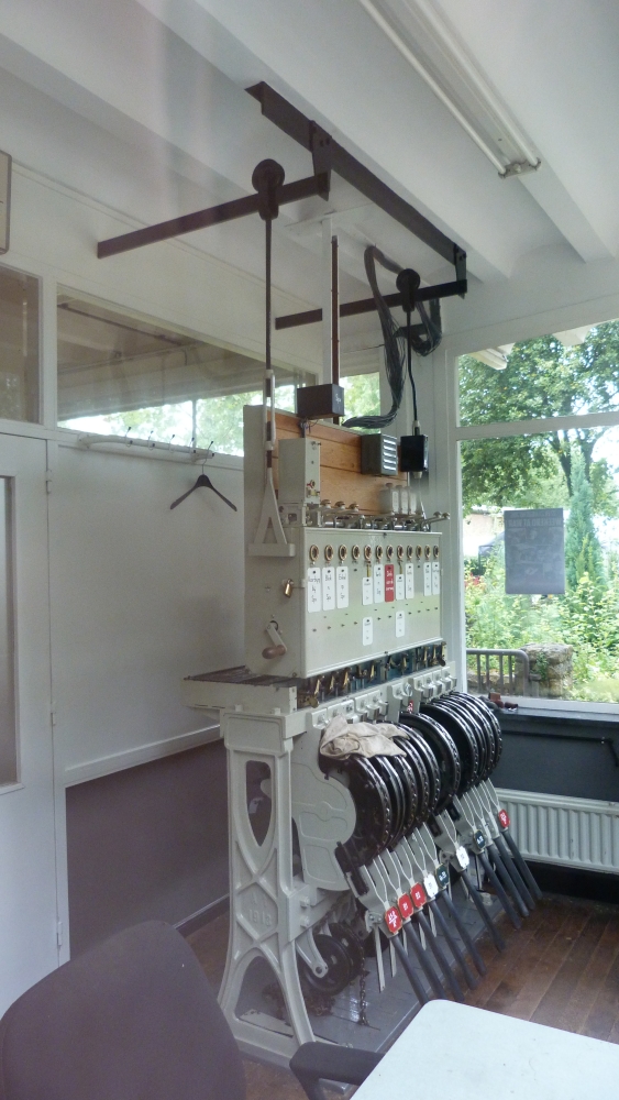
Interlocking frame, post T, Wijlre-Gulpen, 16.8.2015
Lever frame
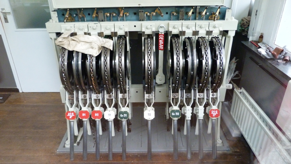
Here is a picture of the lever frame—not all levers are currently operational:
- The leftmost lever controls the home signal A1-2 and its distance signal Av on the Simpelveld side.
- The starter lever B1 is currently not connected (although B1 is standing near the loop track towards Simpelveld).
- Starter lever B2 has a chain, but the chain is not connected to a double wire leading to a signal.
- The next lever is for points no.31 on the Simpelveld side.
- The following lever is marked "Gr.31," where "Grendel" means "facing point lock:" This is the FPL lever for points no.31.
- The next two levers are for points no.32 and its FPL towards Schin op Geul.
- Two more levers for the future starter signals towards Schin op Geul are also not connected and don't even have plates.
- The last lever is for home signal D1-2 (which is called D1 in the track diagram) and its distant signal Dv.
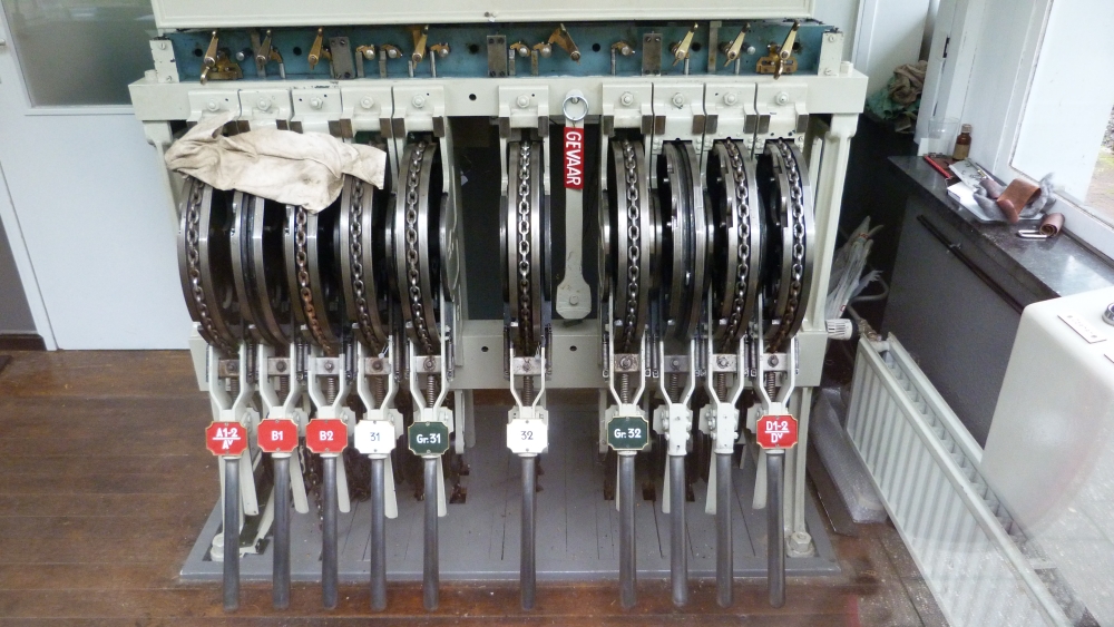
Lever frame, post T, Wijlre-Gulpen, 16.8.2015
http://www.klassiekebeveiliging.com/seinhuizenWij.htm has detailed diagrams and some pictures of earlier frames at Wijlre-Gulpen. One can see that in 2009, there were still the same number of signal levers, as there are signals right now. It seems that ZLSM is in the process of rebuilding Wijlre-Gulpen as a full-fledged crossing station once more, as it was at least until 1986—only now controlled from the single signal box at post T. The following picture shows some details of the still unconnected levers for the future starter signals B1 and B2, as well as the already fully connected lever for points no.31:
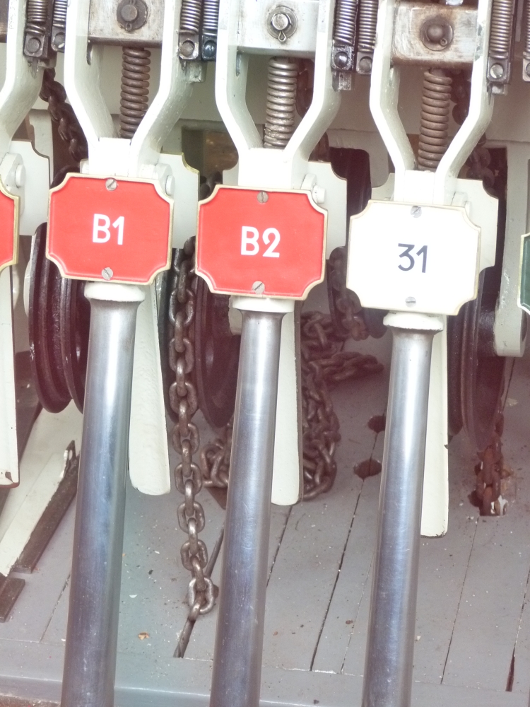
Levers, post T, Wijlre-Gulpen, 16.8.2015
On the other side of the frame, one can see the unlabeled starter levers C1 and C2 near the lever for home and distant signals D1-2 and Dv:
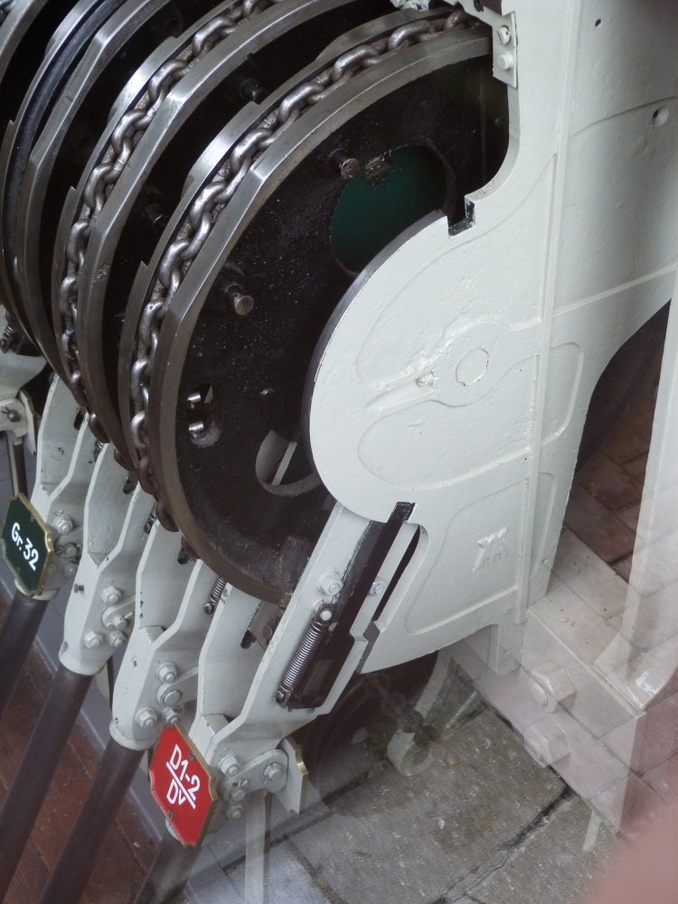
Signal levers, post T, Wijlre-Gulpen, 16.8.2015
In the following detail picture, one can see the small cutouts on the flanges of the chain rolls, where the locking rods coming down from the small levers lock the levers (see diagram in previous posting). Unfortunately, I have not taken pictures of the linkage that moves the small pistons ("Stößer" in the PDF from the last posting) that in turn moves the locking rod above it:
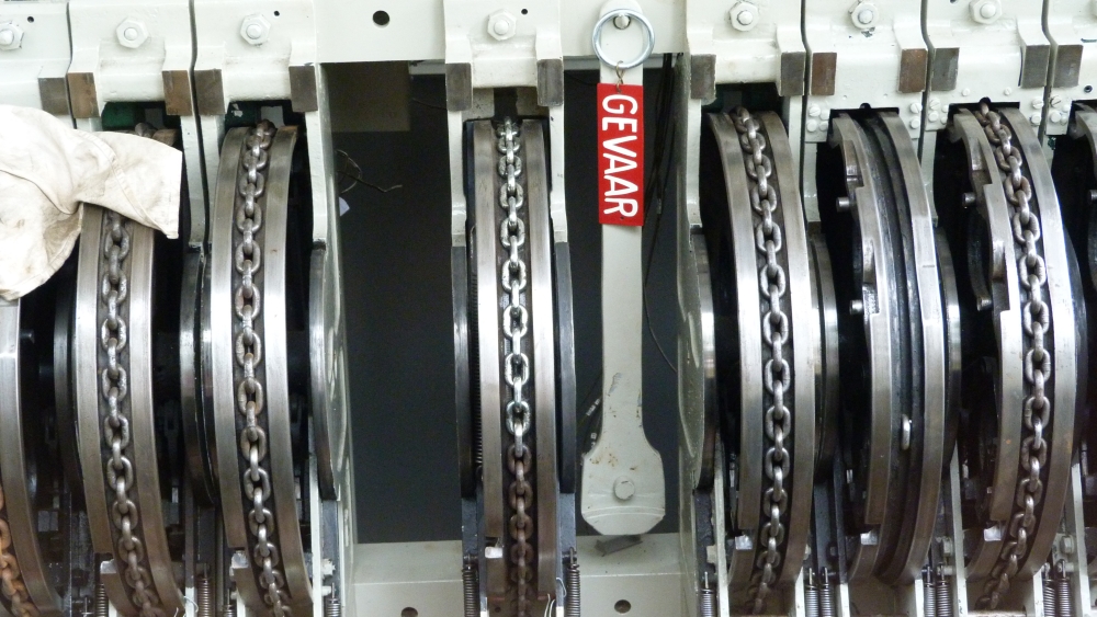
Chain rolls, post T, Wijlre-Gulpen, 16.8.2015
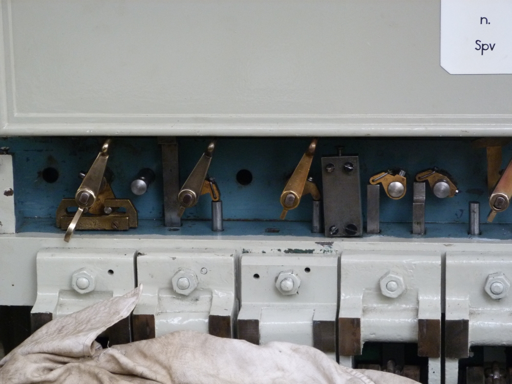
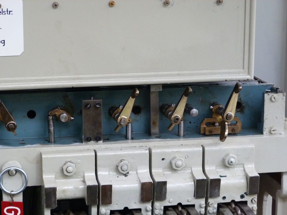
Here is an overview over all levers, with the small route and release levers moving the locking rods above them:
Lever frame and route and release levers, post T, Wijlre-Gulpen, 16.8.2015
Route and signal release levers
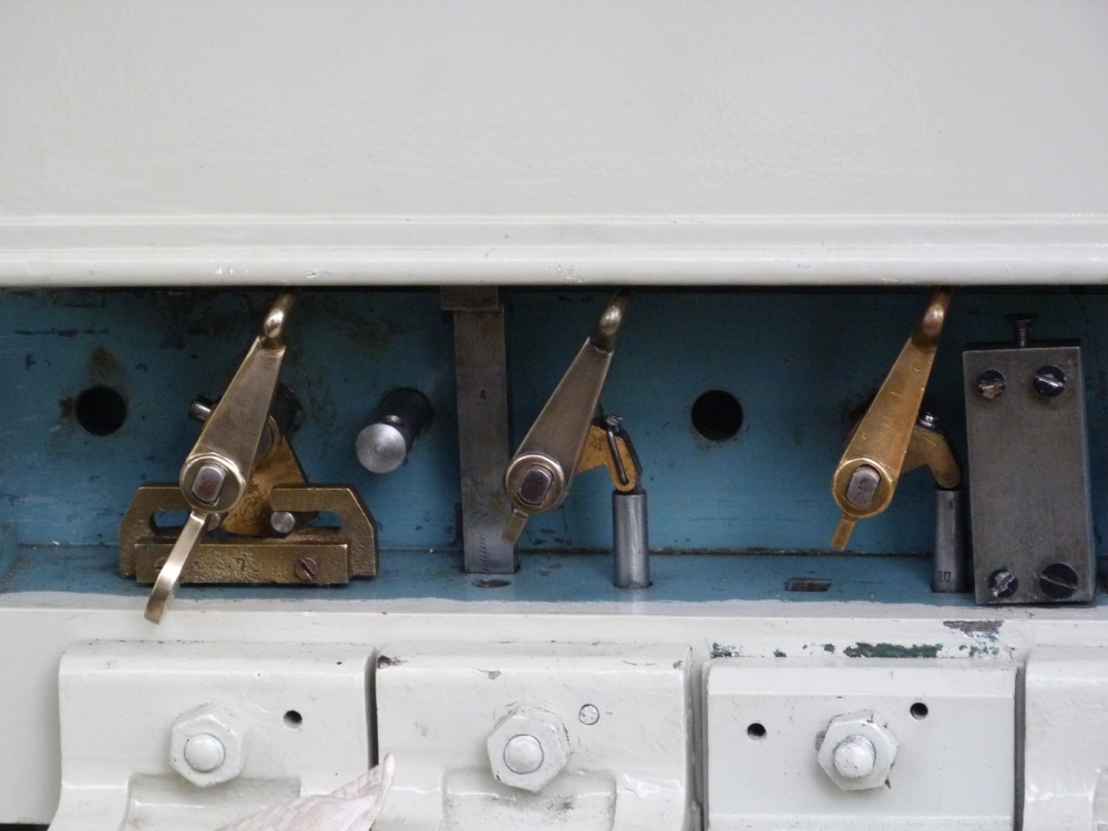
Details of the route and release levers with their locking rods can be seen in the next picture. The two plates above mark the route locking block instruments. Their full names are "route to Simpelveld" and "route to Schin op Geul":
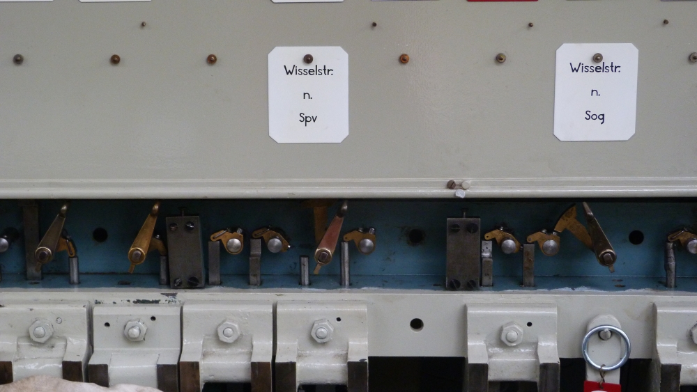
Release levers, post T, Wijlre-Gulpen, 16.8.2015
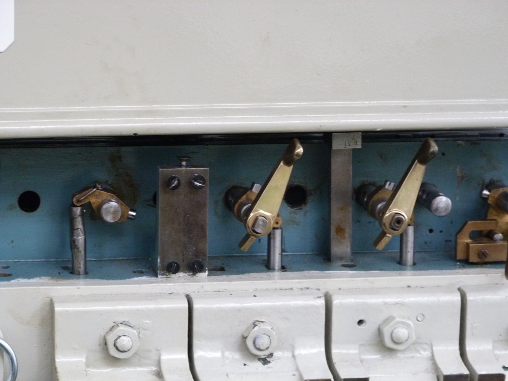
Even more details can be seen in the picture of a signal release levers above a signal lever. I think that this lever can moved either right or left, depending on which track is to be reached by the incoming train. In both cases, the lower locking piece is lifted up and thus unlocks, via its locking rod, the signal lever below. This is an example of a "mechanical or," which is necessary for signals that are cleared for more than one track, and which are one of the more intricate problems when designing mechanical interlocking systems:
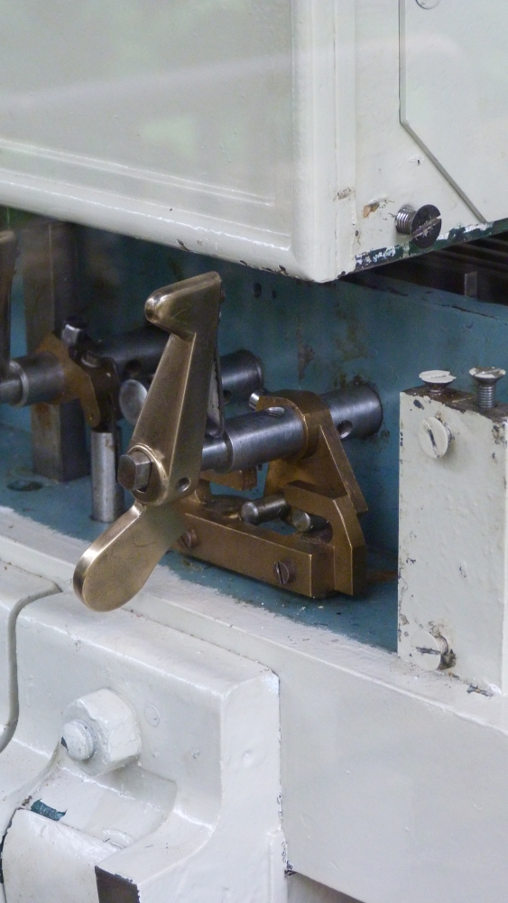
Signal release lever, post T, Wijlre-Gulpen, 16.8.2015
Here are all route and release levers:
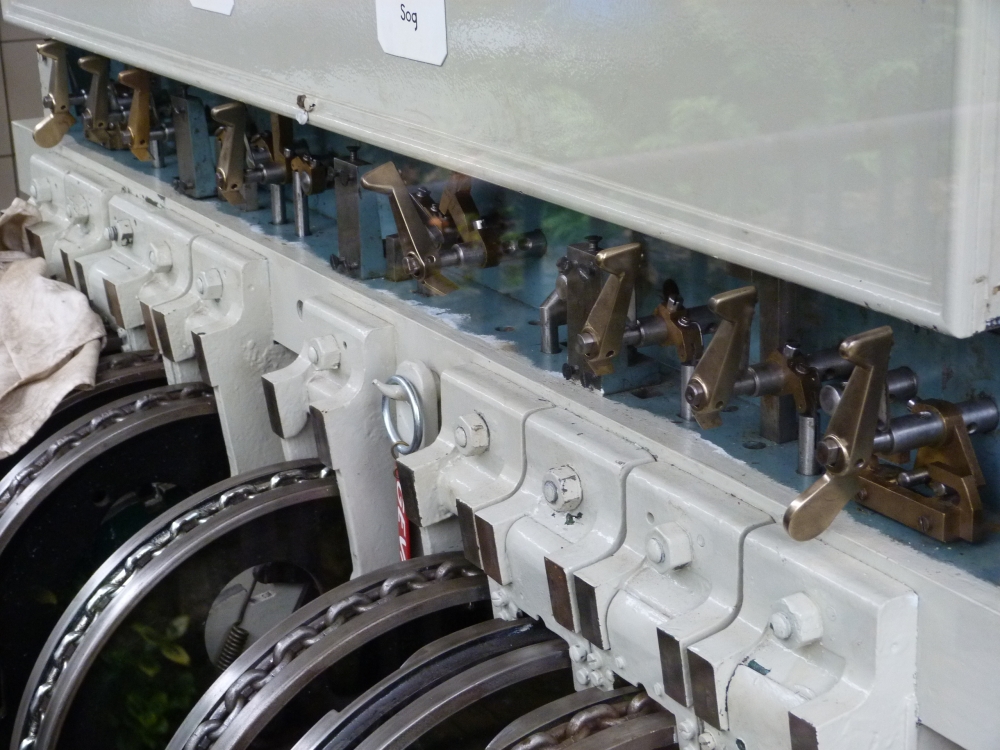
Route and release levers, post T, Wijlre-Gulpen, 16.8.2015
Route and release levers, post T, Wijlre-Gulpen, 16.8.2015
Route and release levers, post T, Wijlre-Gulpen, 16.8.2015
Route and release levers, post T, Wijlre-Gulpen, 16.8.2015
Route and release levers, post T, Wijlre-Gulpen, 16.8.2015
Route and release levers, post T, Wijlre-Gulpen, 16.8.2015
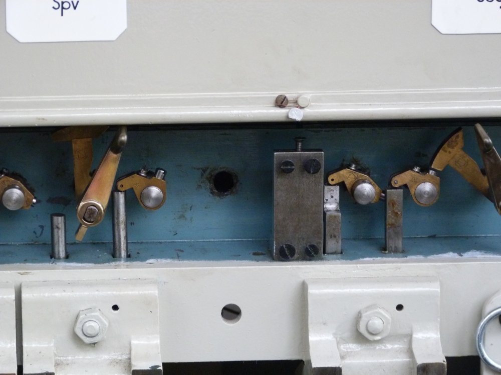
Here is another picture of the release levers for two starting signals—without a "mechanical or"— as well as, on the right, the release lever for the home signal with the "mechanical or":
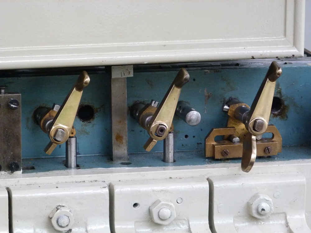
Route and release levers, post T, Wijlre-Gulpen, 16.8.2015
Once again, the whole row of route and release levers:
Route and release levers, post T, Wijlre-Gulpen, 16.8.2015
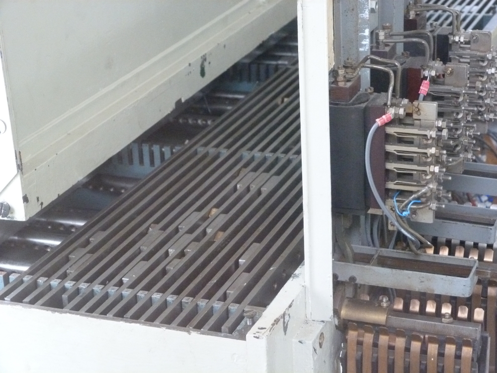
Route bars
On the back side of the frame are the route bars. Additionally, some signal release lever axles move contact sets, and there are a few relays, probably for the block circuits to Schin op Guel:
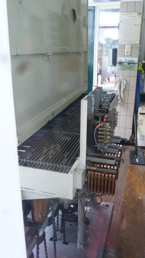
Route and signal bars, post T, Wijlre-Gulpen, 16.8.2015

Contact set, post T, Wijlre-Gulpen, 16.8.2015
Signal bars and relays, post T, Wijlre-Gulpen, 16.8.2015
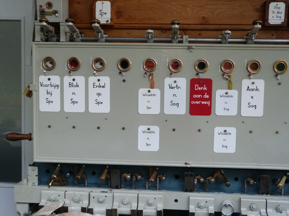
Block instruments
This is the complete set of block instruments. One can see that the route locking instruments ("Wisselstr.") do not have buttons above, so they are blocked together with other instruments. For the next posting, I have to look into the details of working these instruments a little more:
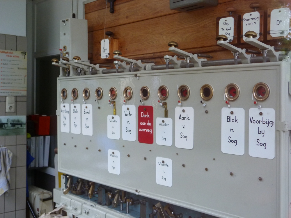
Block instruments and route and release levers, post T, Wijlre-Gulpen, 16.8.2015
Then, I will also try to explain the various types of block instruments:
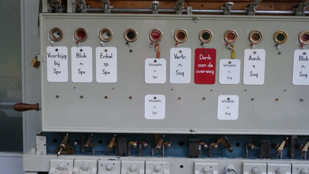
Block instruments and route and release levers, post T, Wijlre-Gulpen, 16.8.2015
Block instruments and route and release levers, post T, Wijlre-Gulpen, 16.8.2015
Block instruments and route and release levers, post T, Wijlre-Gulpen, 16.8.2015
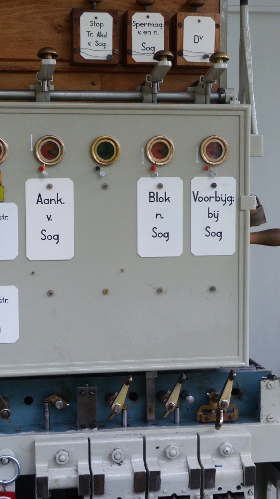
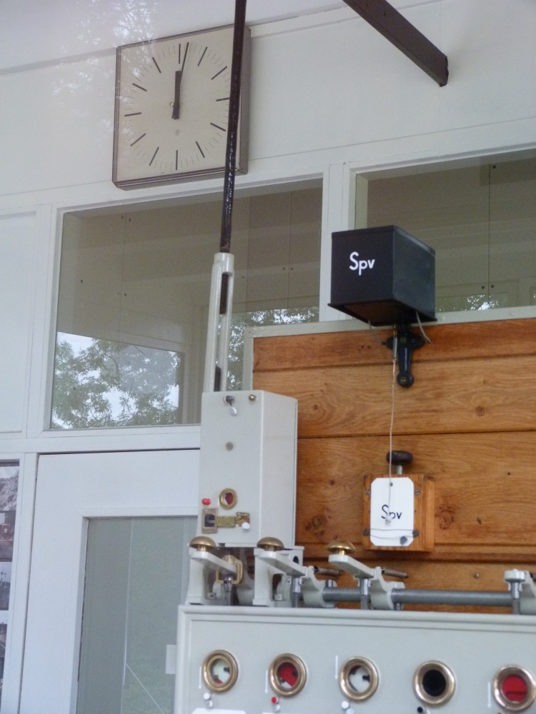
For informing the signalmen about movements or other events, the same bells as in Austria were used: Besides the bell proper, they consist of a lid that falls down when the bell is activated. On the inside of the bell, there is usually some text explaining what has happened. After the signalman has taken the necessary actions, he can close the lid again. If the bell is mounted very high—as can be seen here—, a piece of cord is attached to an eyelet at the end of the lid. Pulling the cord will close the lid. Below the bell, there is a button which probably sends a signal to the opposite bell in Simpelveld:
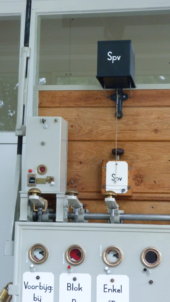
Block instruments and bell, post T, Wijlre-Gulpen, 16.8.2015
To the left of the button, there is a plunger lock (button lock) for the block instrument "Voorbijg." so that blocking back to Simpelveld is only possible if a train has arrived at Wijlre-Gulpen from Simpelveld:
Bell and button lock, post T, Wijlre-Gulpen, 16.8.2015
Barrier control
In post T, there is also a control for the barriers mentioned at the beginning. If I understand it correctly, each barrier can be moved independently (like the gates in Britain)—we will see this also at the gate cranks at Simpelveld:
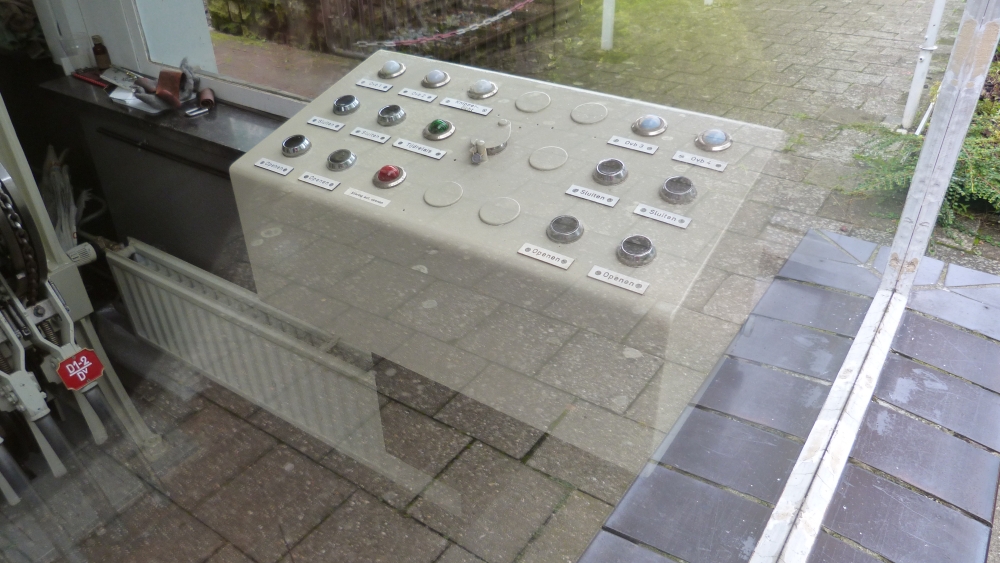
Barrier control, post T, Wijlre-Gulpen, 16.8.2015
Double wires
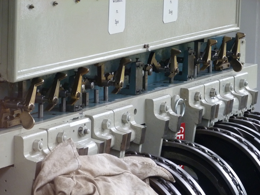
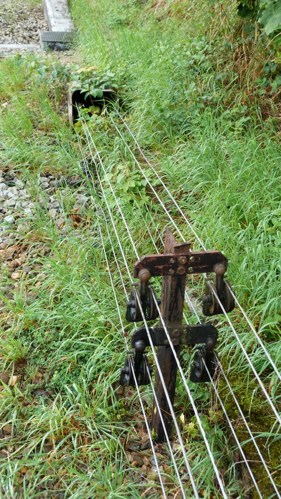
Now, let us leave the treindienstleider's seat and walk outside. The double wires run from the levers below the tracks to rollers that divert them to both ends of the station. At the rollers, chains are inserted into the wires—a distinctly British and Austrian, but not German idea:
Deflection of double wires, Wijlre-Gulpen, 16.8.2015
The chains for the missing starters are already lying in the pit, but not yet pulled around rollers:
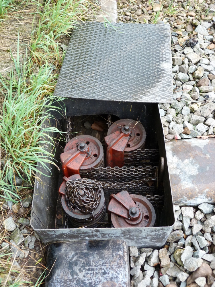
Deflection of double wires, Wijlre-Gulpen, 16.8.2015
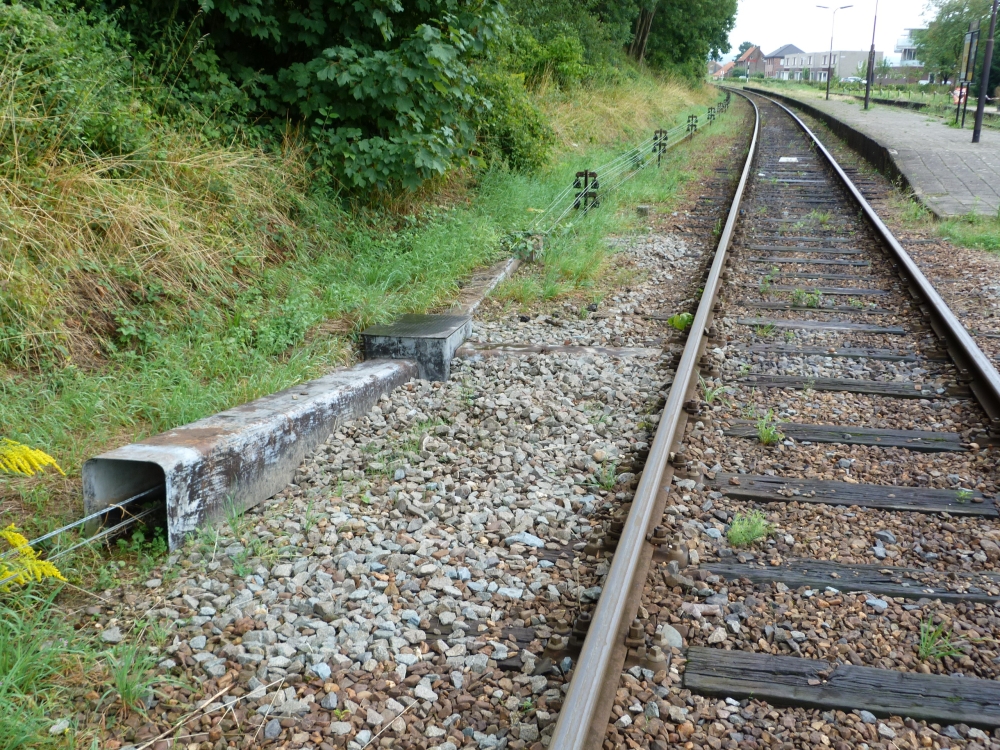
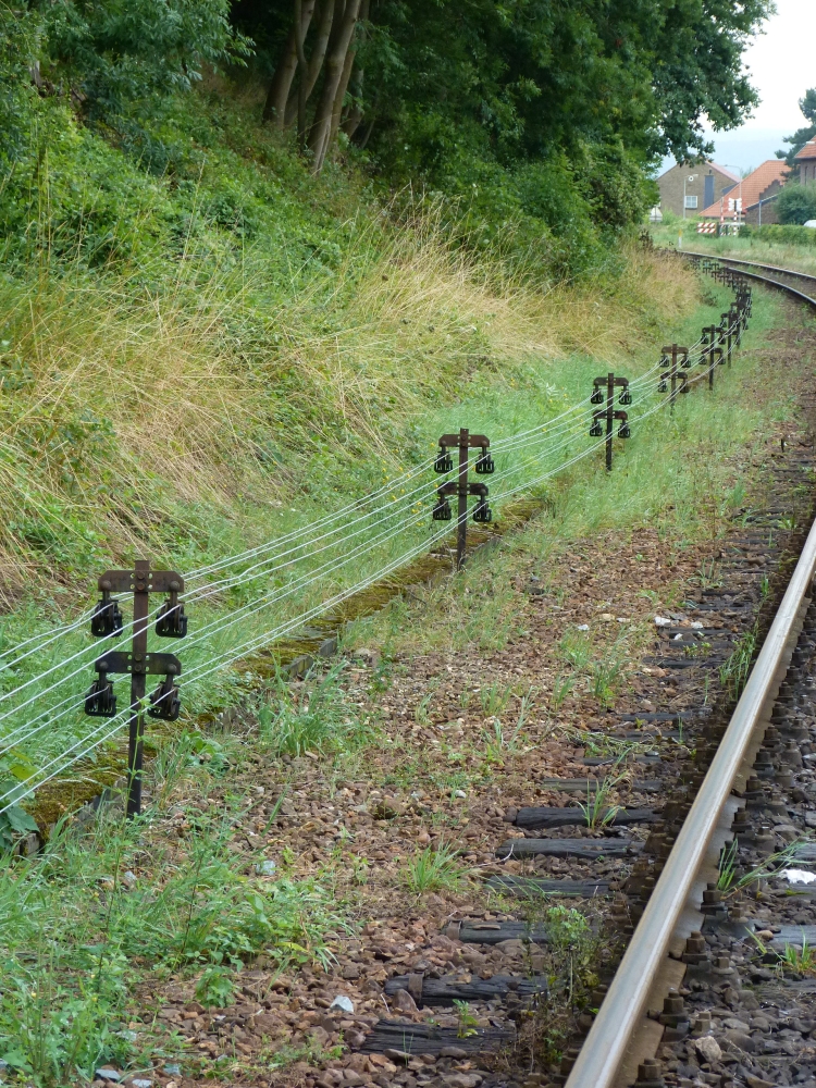
From there on, the wires run along the tracks to points and signals:
Double wires, Wijlre-Gulpen, 16.8.2015
Like in Austria, there are no horizontal rollers for slightly bending wire courses:
Double wires, Wijlre-Gulpen, 16.8.2015
Starter signal
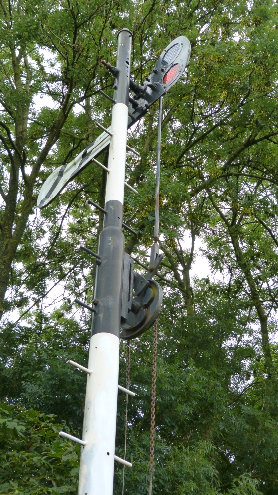
Finally, here are a few pictures of the starting signal C2 at Wijlre-Gulpen:
Starter C2, Wijlre-Gulpen, 16.8.2015
At the foot of the signal, the wires are lead upwards:
Wire deflection at starter C2, Wijlre-Gulpen, 16.8.2015
Somewhat below the signal arm, there is the simple slide mechanism for moving the arm:
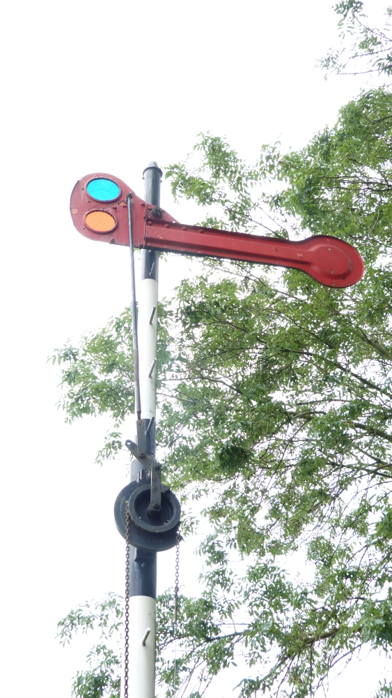
Starter C2, Wijlre-Gulpen, 16.8.2015
Starter C2, Wijlre-Gulpen, 16.8.2015
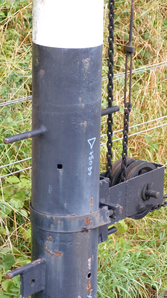
The following picture shows the slide mechanism in some detail. The wheel is turned by the wires, and via the groove it moves the finger on the lever linked to the signal arm. If one of the wires breaks, the wheel will fall to the position where the groove is on the lower side. The groove, however, does not continue around the complete wheel. Therefore, when the wheel falls to its "wire broken" position, the finger is no longer running in the groove, and the signal arm can fall freely to the stop position:
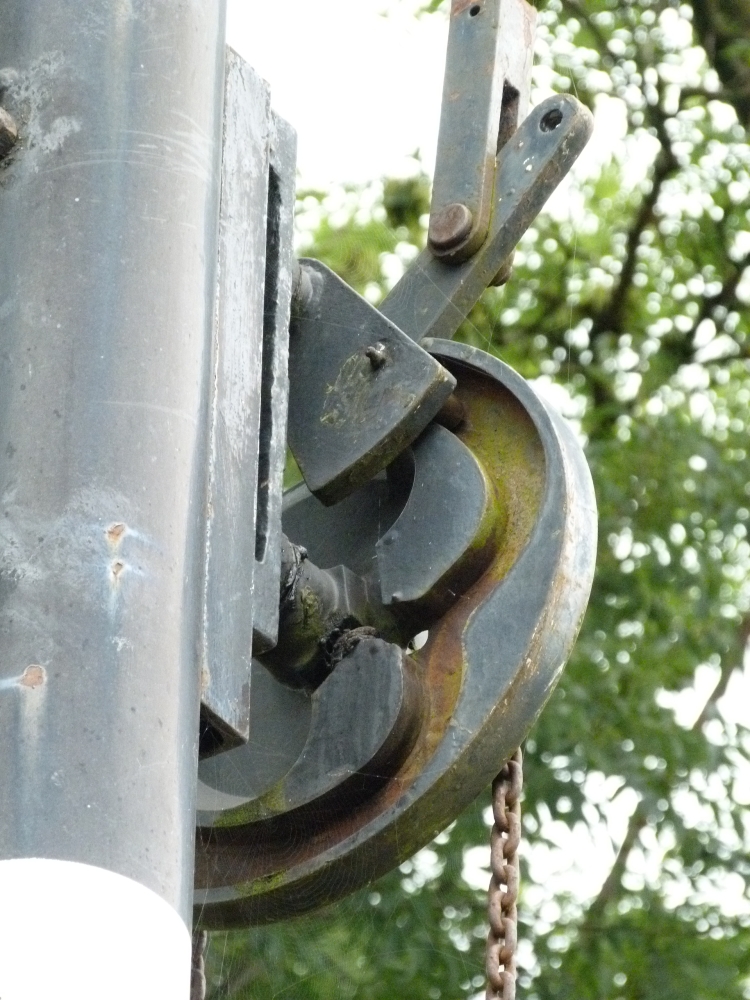
Grooved wheel and linkage at starter C2, Wijlre-Gulpen, 16.8.2015
So much for a set of pictures from Wijlre-Gulpen. The next posting will continue with some more considerations of the topics from the first posting.
No comments:
Post a Comment