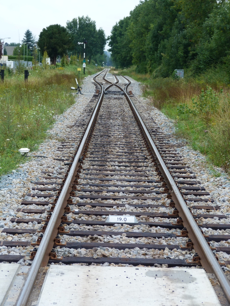
This next posting about Dutch mechanical interlocking technology contains some information about the operation of points, which is distinctly different from their counterparts in Austria and Germany as well as in Britain. For fans of steam engines, I have added a few pictures of ZLSM's SJ 1040.
Remark: In my translation of the original German text, I have tried to use the terms of IRSE from this document.
i) Signal and points mechanisms: with double wires, without tensioners, with chains at bends = "Austrian"
In the Netherlands, points connected to mechanical interlocking frames are in general moved by double wires, following German and Austrian practice. At bends of the wire line, chains were spliced into the wires, as is customary in Austria and also in Britain (but not in Germany, where thin steel cables are used instead). There were no separate tensioners, as they were used in Germany; rather, the linkages for reversing points and moving signal arms had to be constructed in such a way that they would tolerate some slack in the wire lines during hotter times.
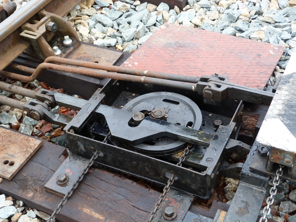
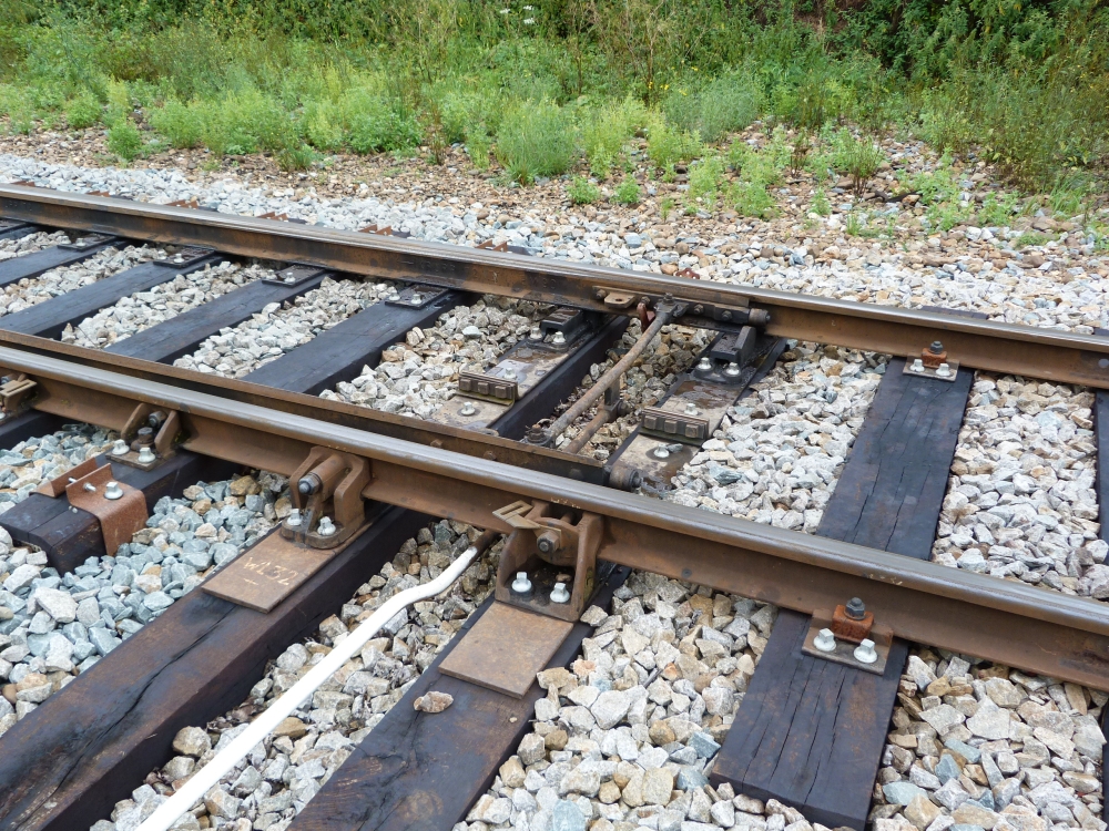
The following picture shows, on the left, the point mechanism and on the right the facing points lock. One can clearly see the chains that are wound around the wheels inside the mechanisms:
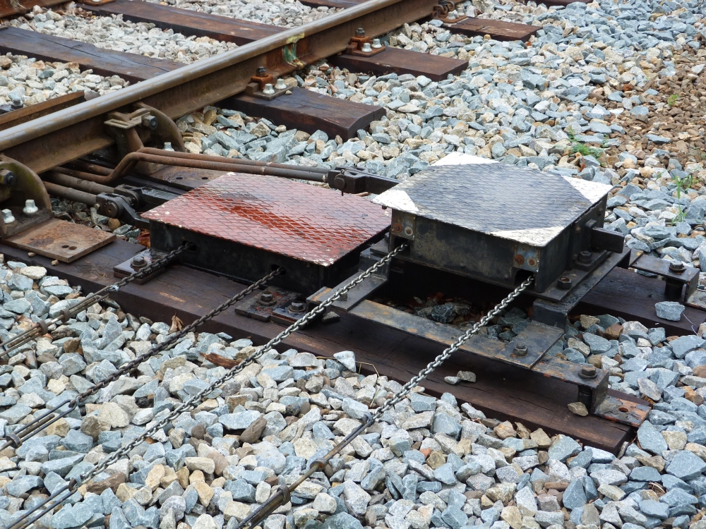
Point mechanism und FPL, points no.32, Wijlre-Gulpen, 16.8.2015
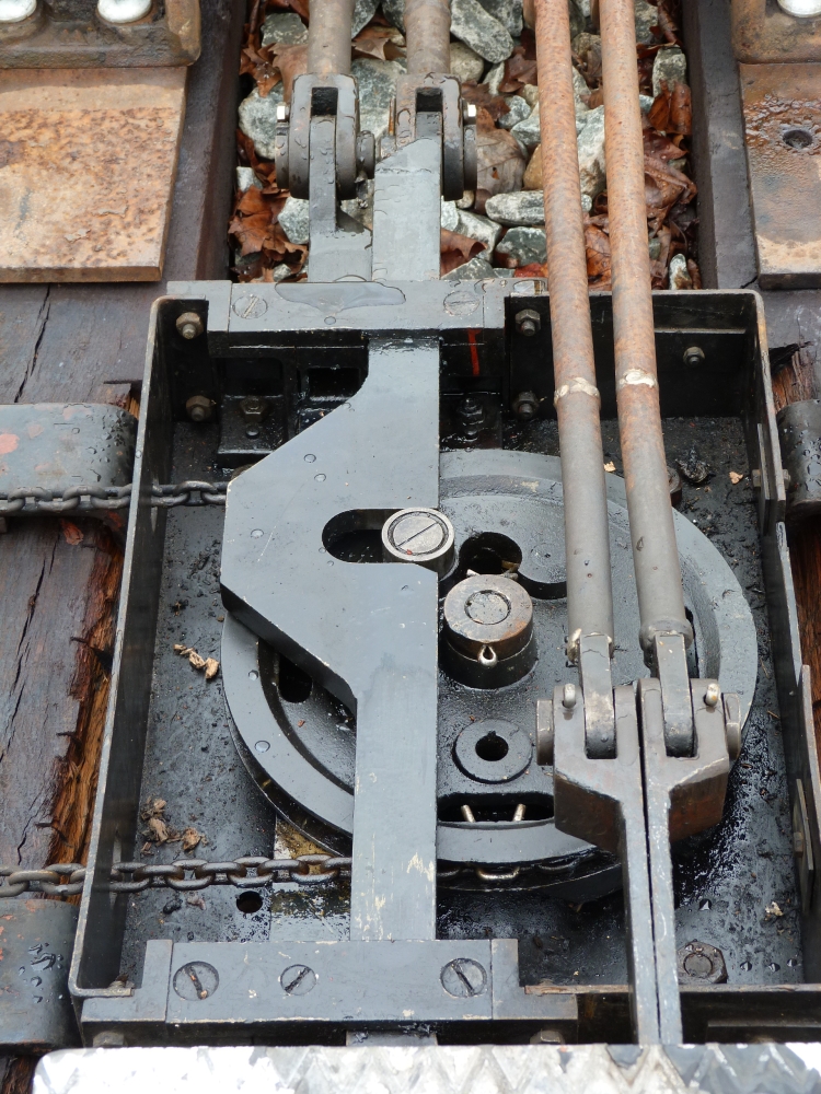
The stepped rods of the FPL run above the point mechanism:
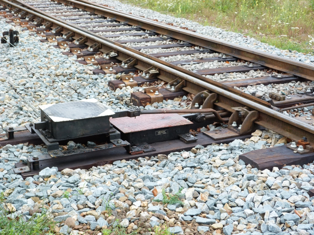
Point mechanism und FPL, points no.32, Wijlre-Gulpen, 16.8.2015
j) Points: Without blade locks = "English", but ...
k) Points: ... can be run through = "Central European"
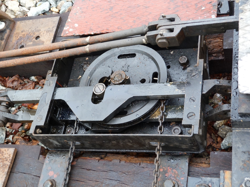
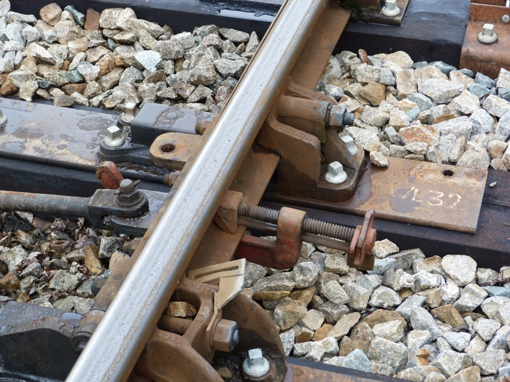
The following picture shows that the rods moving the blades are directly fastened to them via a simple joint. This is in contrast to the blade locks that had to be used throughout Germany and Austria to press the blades against the stock rails:
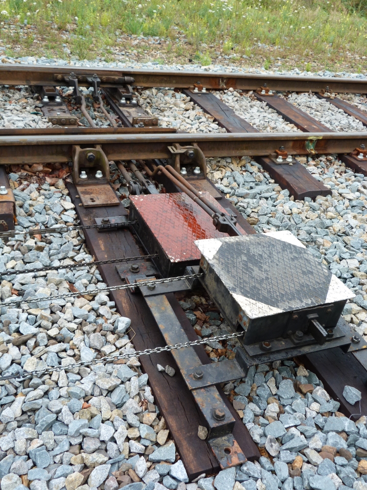
Point mechanism und facing point lock, points no.32, Wijlre-Gulpen, 16.8.2015
Here is a detail of the joints at the tip of a blade: The thinner rod is the detection rod of the FPL, whereas the thicker one is the drive rod of the blade. One can see that both rods are isolated from the blades (the white isolating separators can be seen at the places where the rods are bolted to the joints), therefore these rods can be used with track circuits. It can be clearly seen that no blade locks are in place. There is a small "hump", over which the blade is lifted by a roller at its very tip during reversal. The hump's incline will help the blade to move towards the stock rail more easily. But the distance between the roller and the bottom of the incline is so large (certainly more than one centimetre) that this mechanism cannot be responsible for preventing a dangerous gaping of a blade:
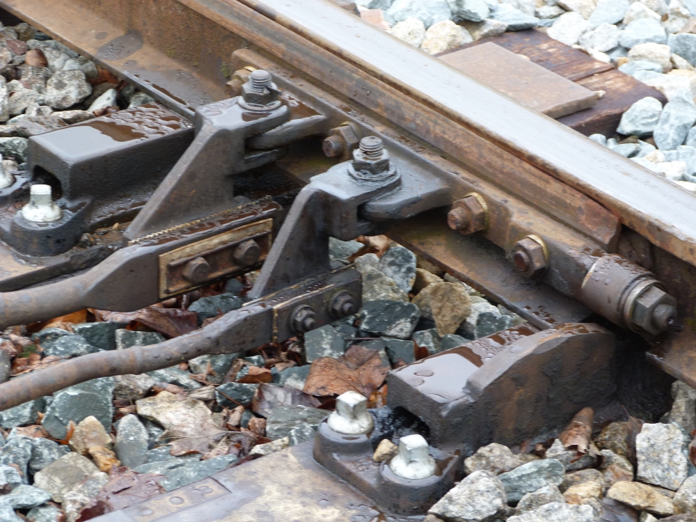
Blade with detection rod and drive rod, points no.32, Wijlre-Gulpen, 16.8.2015
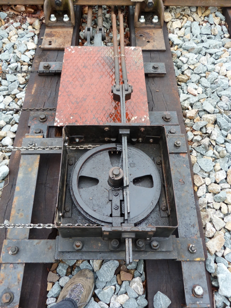
Therefore, we must look somewhere else for the safety-critical element that pushes the blade reliably against its stock rail. To find it, I lifted (against some rules, certainly – I apologize for this) the lid of the point mechanism. Here is what can be seen inside:
Opened point mechanism, points no.32, Wijlre-Gulpen, 16.8.2015
Opened point mechanism, points no.32, Wijlre-Gulpen, 16.8.2015
One can see the peg on the driving wheel that fits into a slot in the drive rod. When the wheel is turned by the wires (which are in turn pulled by the lever in the signal box), the peg will clearly move the rod and therefore the blade that is connected to it. Looking more closely, one can see the following details:
- The peg moves the drive rod of only one blade. The other drive rod is below the wheel, where it is moved by another, similar peg.
- The driving wheel is turned by about 120° when the points are reversed. Thus, the peg is not at the dead center, and therefore, moving the rod by some external force (e.g. on the blades by a train) could move the wheel and hence open the points, which is clearly very dangerous.
- However, the peg is not directly attached to the driving wheel. Rather, it sits on a separate small lever. Hence, moving the drive rod from the blade will not turn the driving wheel, but try to move that small lever. If, below the wheel, this lever rests against some fixed stud on the bottom of the mechanism, the drive rod cannot be moved. If, additionally, the housing of the point mechanism is securely mounted on two ties that are also rigidly connected to the stock rails, the blade cannot move from its position and hence will be tightly pressed against or at least be very near to its stock rail.
- This decoupling of the position of the drive rod from the driving wheel is necessary for another reason: Because of temperature expansion and contraction, the double wires cannot position the driving wheel at a precise angle at the end of its movement. In other words, the linkage must tolerate some slack in the movement up to the driving wheel.
- Last, but not least, the peg moving the drive rod of the open blade could be freely movable so that the blade could turn the wheel. This would allow running through the points without destroying the mechanism—a typical requirement in Central Europe!
Unfortunately, I cannot and could not look below the driving wheel, so I do not know how much of my guesses above is true. Insofar this point mechanism is quite "Austrian"—the mechanisms in my home country were enclosed in casings, in contrast to the easily "readable" British and German point mechanisms.
Here is a last picture:
Opened point mechanism, points no.32, Wijlre-Gulpen, 16.8.2015
In contrast to the point mechanism, the facing point lock is much simpler: A rim on the turning wheel locks into cuts in the detection rods, which are therefore unable to move and fix the blades in their respective positions. However, the detection rods in the following picture have cuts pointing upwards—which could not be locked by the wheel that is below the rods. Most probably, someone reused rods from another set of points by turning them over and filing new cuts
Update 2.11.2016: The cuts on top are most probably not there because of a reuse, but because a a second wheel on top could be used to lock the blades for a route into the loop track. This was (and will be) necessary if Wijlre-Gulpen is used as a passing station. For such FPLs with two wheels (and four chains coming out), see the posting of Simpelveld:
Opened facing point lock, points no.32, Wijlre-Gulpen, 16.8.2015
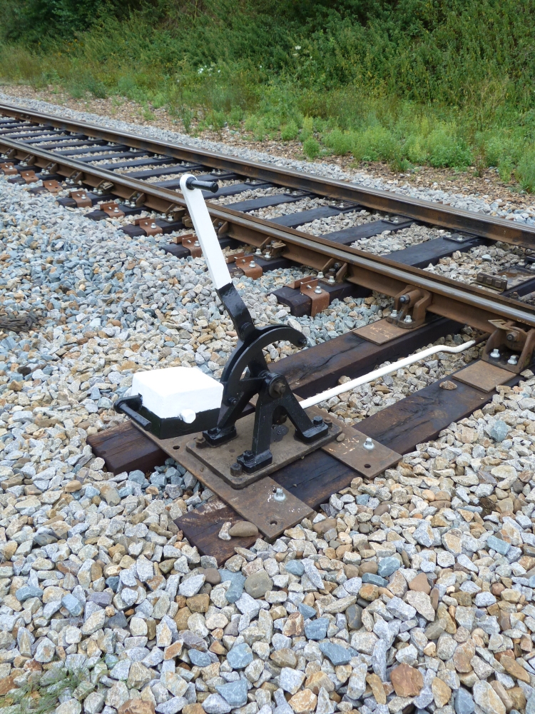
l) Locally operated points: with weighted lever = "Central European"
The next picture shows a locally operated set of points. Because the line went from double track to single track at Wijlre-Gulpen, the separation points are of a symmetrical design. When the line to Schin op Geul was also single-tracked, the relative position of the tracks was not changed, but the separation points now led to a stub track. Last, these points were moved behind the crossing, as can be seen in the first of my postings about Dutch interlockings:
Locally operated points, Wijlre-Gulpen, 16.8.2015
The lever is weighted for pressing the blade against the stock rail. Moreover, a manual lever can (probably) be used to add more pressure—untypical for Central Europe:
Locally operated points, Wijlre-Gulpen, 16.8.2015
Locally operated points, Wijlre-Gulpen, 16.8.2015
When a train passes such a set of points, facing point locks are definitely necessary, also at small speeds. However, this specific set of points is secured by a clamp:
Blade clamp on locally operated points, Wijlre-Gulpen, 16.8.2015
Finally, for steam-engine friends, here are a few pictures of ZLSM's SJ 1040, an ex-Swedish engine pulling museum trains between Schin op Geul and Simpelveld:
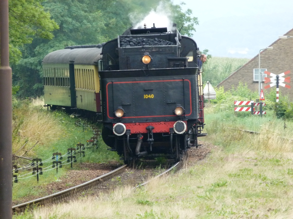
SJ 1040, Wijlre-Gulpen, 16.8.2015
I love this type of engine with its interior driving rods and Walschaerts gear, as one can see the elegant wheels without any view obstruction. This type's highly mounted ("Gölsdorf style") boiler and the narrow wheel rims underscore the elegance even more:
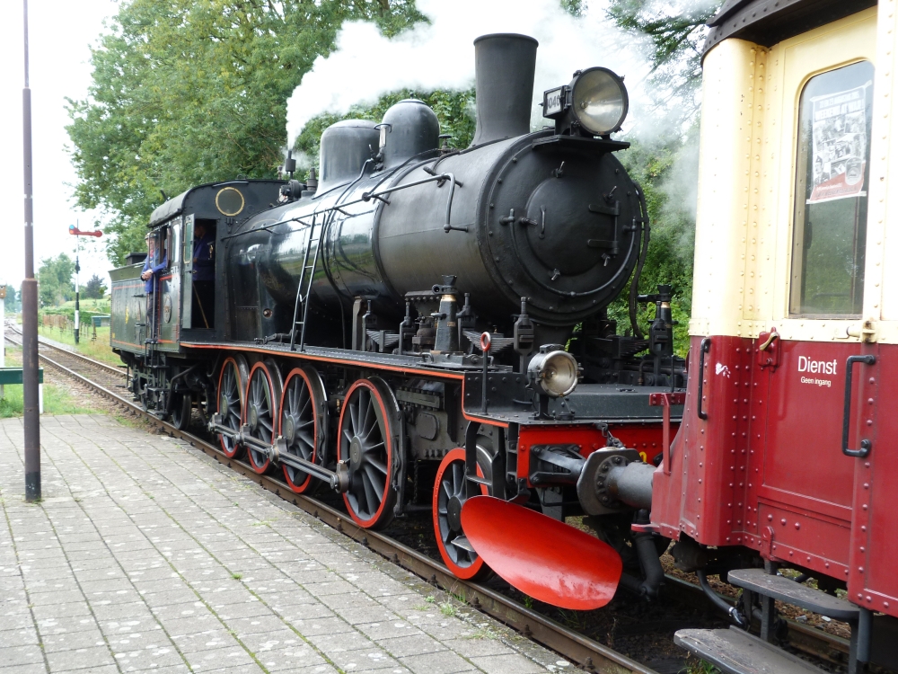
SJ 1040, Wijlre-Gulpen, 16.8.2015
Between the frame bars, one can see the parts of the Walschaerts gear and, a little bit lower, the slide of the crosshead:
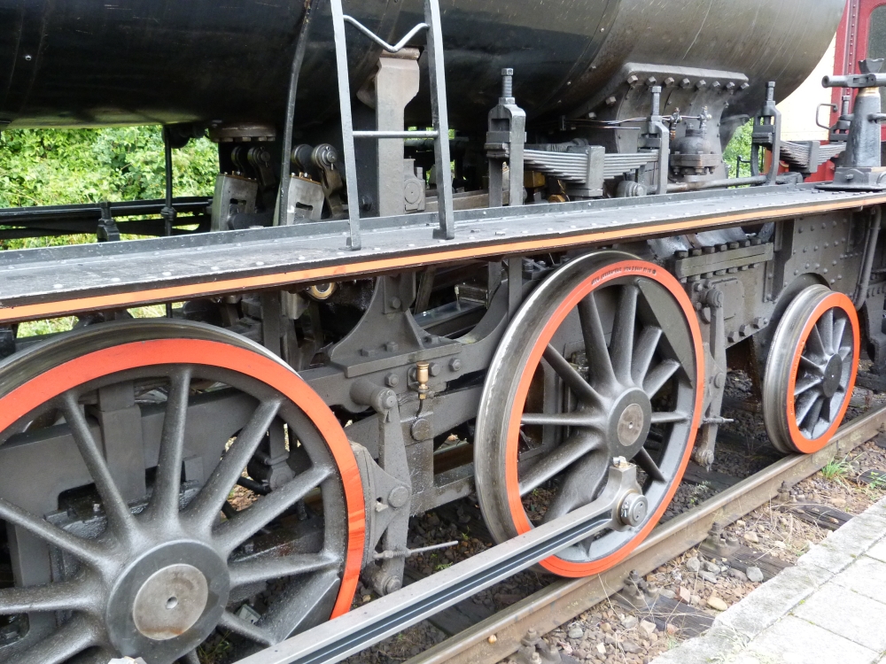
SJ 1040, Wijlre-Gulpen, 16.8.2015
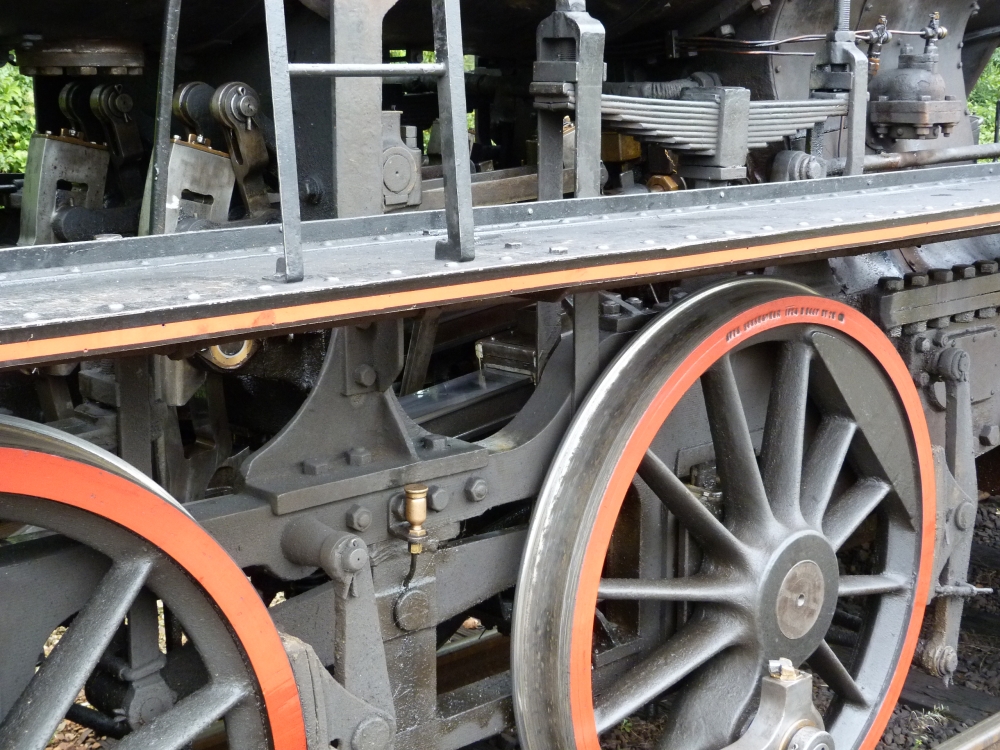
SJ 1040, Wijlre-Gulpen, 16.8.2015
No comments:
Post a Comment