After quite some time, here is the next posting about Dutch mechanical interlocking. The topic of this posting is "block instruments," with a focus on single line block working.
e) Station block: Siemens block instruments, "German" version; with "Austrian" bells
The safe communication between posts, both for
- communication between the posts of one station, i.e., between the post T and the signal boxes proper,
- as well as for block working on the line,
- German instruments have a small eye in the visible part of magnetic anchor, Austrian ones are without that eye;
- German instruments use only red (for "instrument blocks something") and white (non-blocking position), whereas Austrian instruments use also other colours.
- In Germany, special DC instruments were used as route locks, whereas Austrian interlockings used common AC instruments.
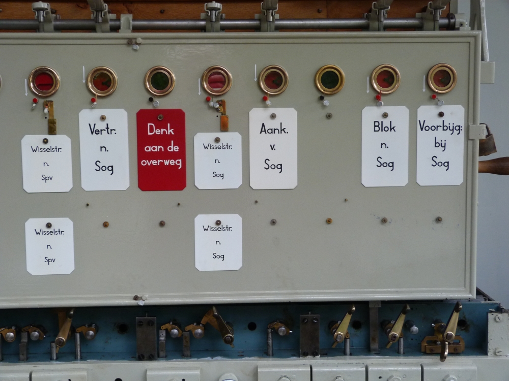
Block instruments, post T, Wijlre-Gulpen, 16.8.2015
Block instruments, post T, Wijlre-Gulpen, 16.8.2015
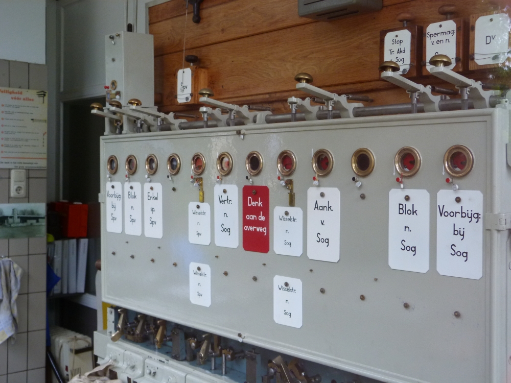
Block instruments, post I, Simpelveld, 16.8.2015
Block instruments, post I, Simpelveld, 16.8.2015
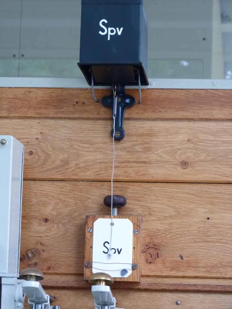
Besides communicating safely via block instruments, it is also necessary to inform another post about some request – e.g., requesting that an instrument is blocked so that a train is permitted into a track or line section. The safety of this operation would be guaranteed by the mechanical locks and electrical circuits of that block instrument, so the request itself could be transmitted unsafely. Of course, in many instances telephones were used for this type of communication, but for routine interactions, simple bells were widely used. Those bells were of the "Austrian" design, where a lid falls down when the bell is activated from the sender. The purpose of this design is that the information about the request was permanent, so the signalman would be informed even if he happened not to be near the bell when it sounded (e.g., throwing some locally operated points). In many cases, the type of request was also stenciled on the inside of the lid, so that it could be easily seen when the lid was dropped. In Austria, it was customary to close the lid simply by pushing it up with the hand. In the Netherlands, the bells were apparently mounted so high that a short string was attached to a small lever at the lid's end; a short pull on the string would then close it:
Bell, post T, Wijlre-Gulpen, 16.8.2015
f) Block working: Siemens block instruments = "Central European"
Around 1870, Carl Frischen invented the Siemens block instrument for block working. The Dutch railways used these instruments for protecting trains against opposing as well as following trains. The mechanically intricate design uses abut twelve pulses of an alternating current for transmitting a single bit, which makes this method of communication so safe that no overlapping layer of communication is needed – in contrast e.g. to the British block instruments, which predominantly use direct current and are used together with a required system of bell signals to provide the necessary safety against failure. The Siemens block instruments lock the signal levers of all signals into a line section, as long as this section is occupied by a train. A consequence of this design is that a failure of some part of the system makes it impossible to clear the signals, so that in such a case trains must receive orders to pass signals showing a stop indication.
g) Coupling of station block and line block working: Decoupled = "German"
In Austria, some block instruments used for communication between the signal boxes of a single station are also an integral part of the line blocking system. For example, in Austria, the information that a section of a line is occupied is sent at the same time and with the same instrument as the command from the train director to the local signal box for clearing the starting signal (blocking of the "Ba" instrument in earlier types, and of the "A" instrument in later installations). Similarly, the line is signalled as clear with the same instrument that also locks a signal box's home signal after a train has arrived. In contrast to this interlocked way of operation, the actions for station and line blocking were completely separated in (standard) German installations, and this was also the case in the Netherlands. The advantage of this is that a failure in one system (station or line blocking) does not interfere with the operation of the other; the disadvantage is of course that the separate instruments are somewhat more expensive.
The decoupled operations in the Netherlands require two block instruments for each section with line blocking, one on each side:
- One instrument transmit the information "line occupied" to the other side, thereby locking its own signal in the stop position.
- The second instrument on the other side is used to signal back "line clear", which unlocks the signal.
h) Single line block working: permission per train = nearer to "Austrian" practice
On single-track lines, it is not only necessary to protect a train against a following train, but also against opposing trains. Actually, opposing trains need not create a safety risk: For example, on a single line with three sections, two trains might enter the first and last section from opposing sides, as long as they are prevented from concurrently entering the central section. However, such a situation is of course very undesirable.
Essentially, there are two methods of securing against opposing trains:
- One method uses "single permits:" The signal box on the far side sends a signal to the other side that a single train may enter the single line, thereby locking its own signal so that it cannot send an opposing train down the line. In simple cases, the permit is given over telephone ("telephone block working"), but more advanced installations use block instruments for this.
- The other method uses a "direction permit:" At one time, one or the other side is allowed to send trains on the line. No separate action is needed for the next train following in the same direction. Only when the direction of travel has to change, one side must give up its permit to the other side.
The line between Wiijlre-Gulpen and Simpelveld was the last Dutch line using single permits. The operations of this system is explained with a sequence of images on this page at klassiekebeveiliging.com (scroll down to the middle of the page, there are two arrows for clicking through the seven steps). However, I think it is easier to understand the workings of this system if one looks at the electrical connections between the block instruments. I have reverse-engineered a rough diagram of the circuits on both sides of the single line. The diagram uses the following letters:
- B = "Blok" - this is the signal-blocking block instrument at the entry to the line.
- E = "Enkel" = "single" (permit) - the block instrument for permitting one train into the line.
- V = "Voorbijgang" - the instrument for signalling "line clear".

However, I think that is not really easy to understand the block system's working from this diagram. Therefore, I have created a simpler diagram where I left out some connections which—I believe—were added in later times. Thus, the following diagram shows the "pure" circuits needed for single-line blocking. One can see that in this basic form, three instruments are interconnected in a triangle of circuits. The operation is as follows:
- When no train is near the line, the Blok instruments are blocked and lock their respective signals. Thus, no train can enter the line.
- If a train is to be permitted into the section, the Enkel instrument is blocked on the far side, which unblocks the Blok instrument on the near side. This in turn unlocks the signal lever so that the signal can be cleared.
- After the signalman has returned the signal lever, he blocks the Blok instrument, which will now unblock the Voorbijgang instrument on the far side so that it shows red (for "line occupied"). The Enkel instrument remains blocked, so that the far side cannot permit another train into the section.
- When the train leaves the section, the Voorbijgang instrument can be blocked, which will in turn unblock the Enkel instrument at the same signal box. All instruments now have the position they had at the beginning.

The circuits just described will prevent that a following train can enter the line while it is occupied. However, it will not hinder the other side of also blocking its Enkel instrument, thereby allowing an opposing train into the section. But this problem is easy to solve: As long as one Enkel instrument is blocked, it must interrupt the circuits of the other Enkel instrument—then, it is impossible to permit two opposing trains into the section.
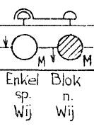
However, this solution has a disadvantage: It is still possible to press the button of the other Enkel instrument, which will put the instrument in a position where it is "half locked" (I'll skip the details of why the instrument will react like that). Therefore, the system uses another option: When the Blok instrument is blocked in the second step, the Enkel instrument near it is also blocked (via a mechanical linkage between the two instrument buttons). This is indicated by the dark-red bent line in my first diagram. I have chosen this representation because it mimics the official symbol for mechanically connected buttons, as can be seen in this detail from Simpelveld's original operating manual:
The unblocking of the Enkel instrument of the opposing direction is done by the third step, i.e., by the blocking of the Voorbijgang instrument on the opposite side.
The operating manual from Simpelveld
The 1960's operating manual of Simpelveld's interlocking apparatus can be downloaded from this page at http://www.klassiekebeveiliging.com as a PDF file (klick "BVS" in the website and then "S"). The manual describes all operations necessary for train runs to and from Simpelveld. However, the necessary actions are sorted by post, and hence it is somewhat difficult to get an understanding of which parts of the interlocking frames work together. For the runs on the Wijlre-Gulpen side, I have therefore attempted to assemble them in a single page which shows all the actions on post T and post II (a click on the diagram opens a readable PDF file):

Although ... the information collected there is probably only of interest for severely afflicted signalling fans.
The next posting will show pictures for another topic, namely the linkage used for reversing points.
No comments:
Post a Comment