In this posting of the ZLSM's signal boxes, I show pictures of the frame on post I, consider missing connections to block instruments on post T, and finally present pictures of a train run.
Here one can see the signal box:
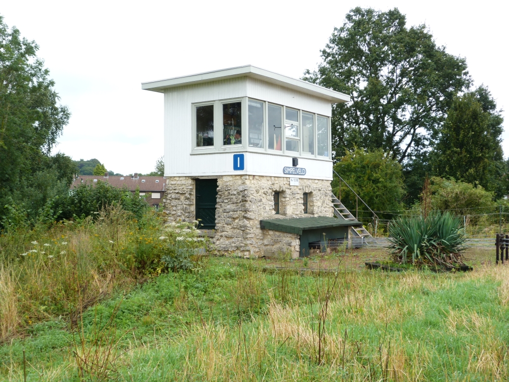
Post I, Simpelveld, 16.8.2015
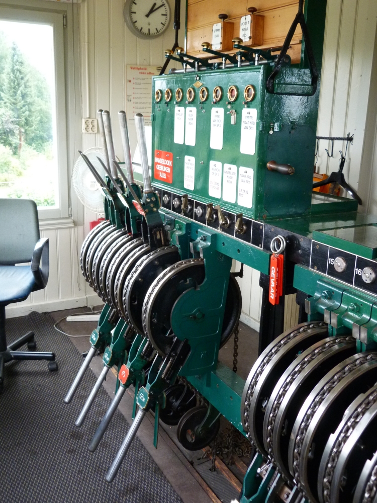
Inside, there is this Siemens&Halske type 3414 frame:
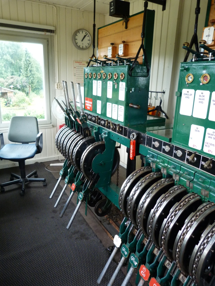
Lever frame and block instruments, post I, Simpelveld, 16.8.2015
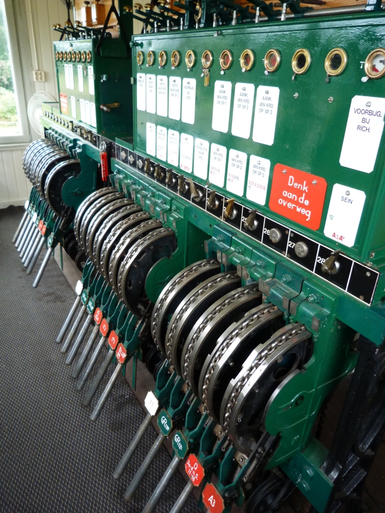
Lever frame, post I, Simpelveld, 16.8.2015
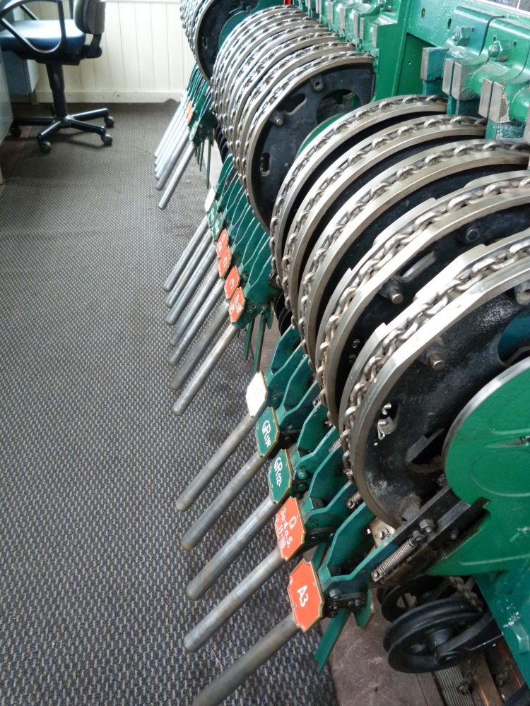
From left to right, the levers on the left side of the frame are as follows:
- Points lever 15
- FPL lever 15R (the sign says "GR15R" – GR is short for "Grendel", meaning "lock")
- FPL lever 14L
- Points lever 14
- FPL lever 14R
- Shunting signal lever R1o,2o
- Starter signal lever CR3
- FPL lever 16R
Lever frame left, post I, Simpelveld, 16.8.2015
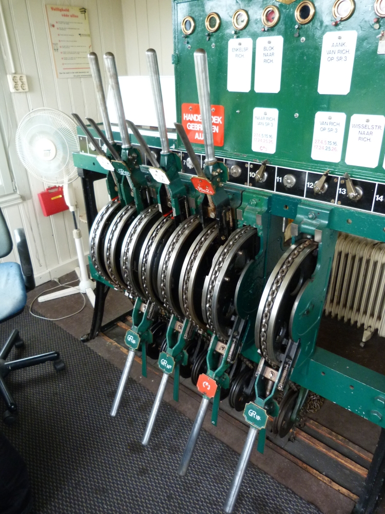
Lever frame and block instruments, post I, Simpelveld, 16.8.2015
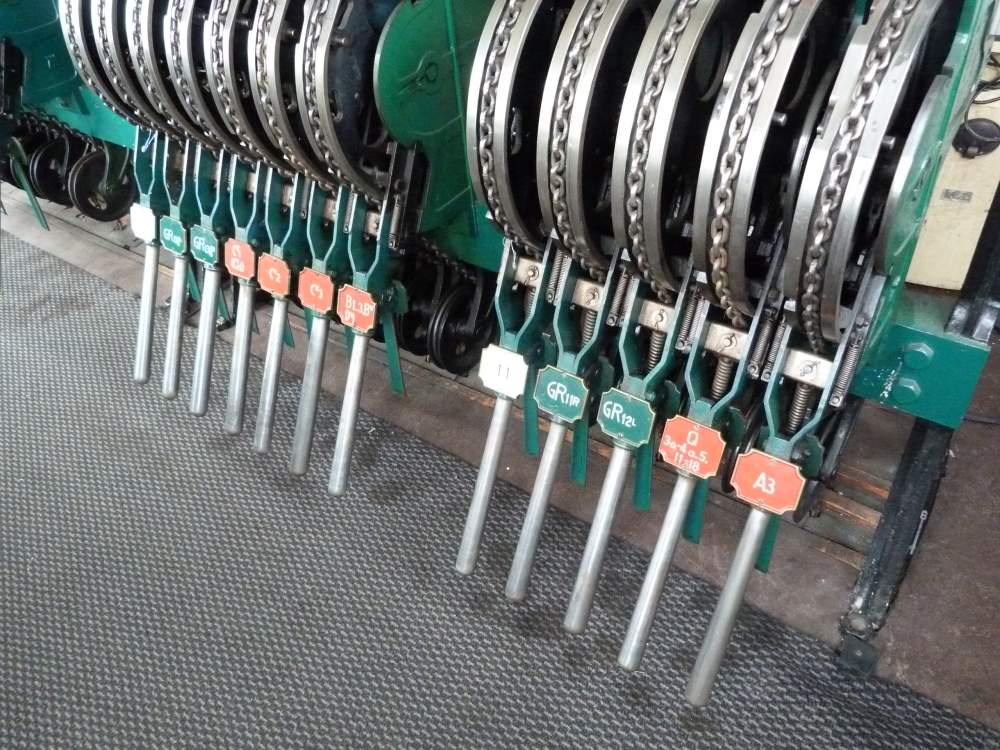
On the right half of the frame, the following levers are mounted:
- Points lever 13A/B
- FPL lever 13A/BL
- FPL lever 13A/BR
- Starter signal lever CK1(CvK1)
- Starter signal lever CK2
- Starter signal lever CK3
- Home signal lever B1-3,Bv,Dv1
- Points lever 11
- FPL lever 11R
- FPL lever 12L
- Shunting signal lever Q3o,4o,5,11-18
- Home signal lever A3
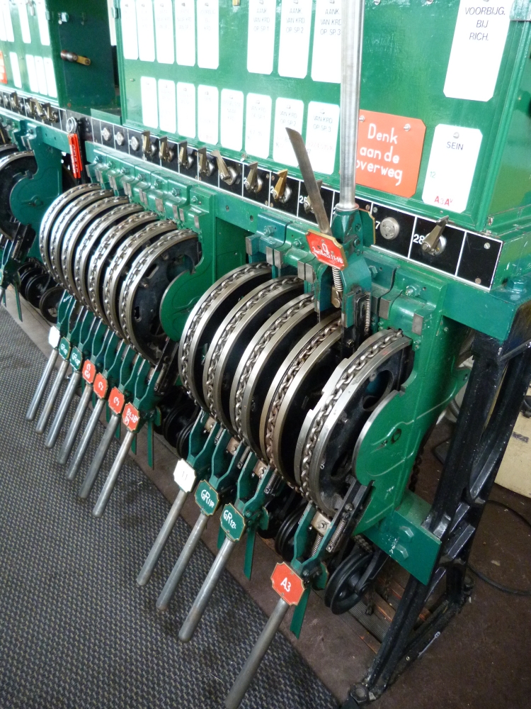
Lever frame right, post I, Simpelveld, 16.8.2015
Lever frame, post I, Simpelveld, 16.8.2015
The following picture of the track plan on post I is somewhat distorted, to prevent light reflexes—it is only readable in the full resolution image:
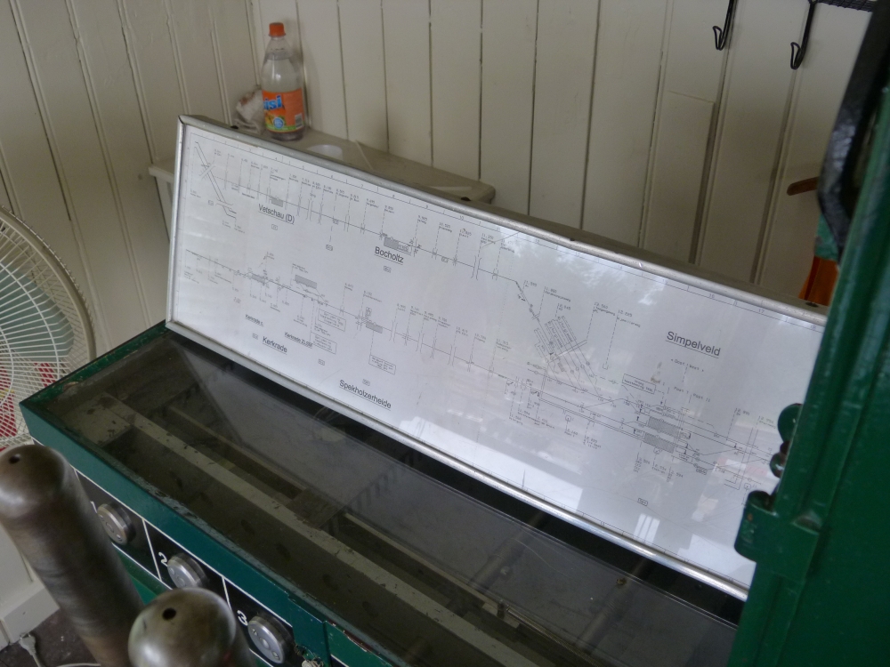
Track plan, post I, Simpelveld, 16.8.2015
The following detail shows that three signal symbols differ from their real counterparts::
- The starting signal at track 3 shows two arms.
- The shunting signal Q is shown near track 1 and guards all tracks, therefore its name is Q 1-4 Oost, 5, 11-18.
- The low shunting signal R1-2 is missing.
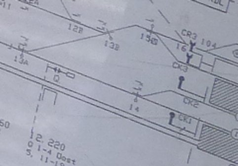
Track plan detail, post I, Simpelveld, 16.8.2015
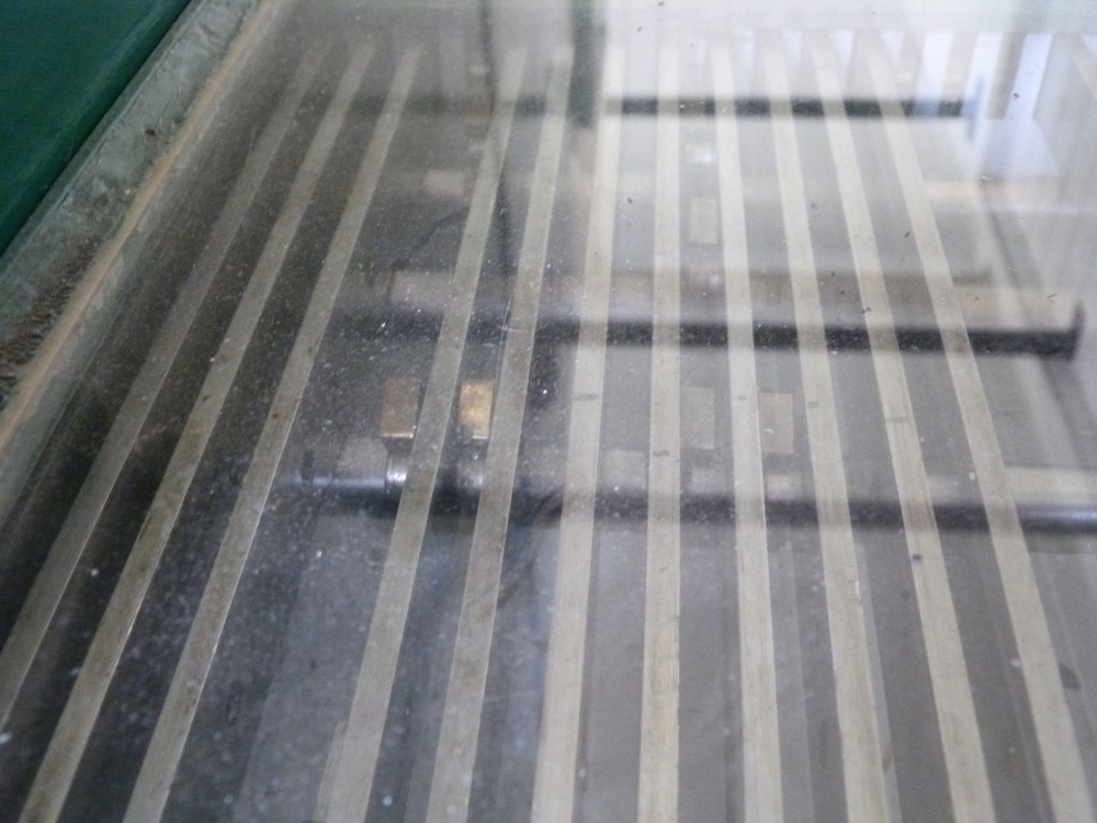
The locking bed is covered with glass:
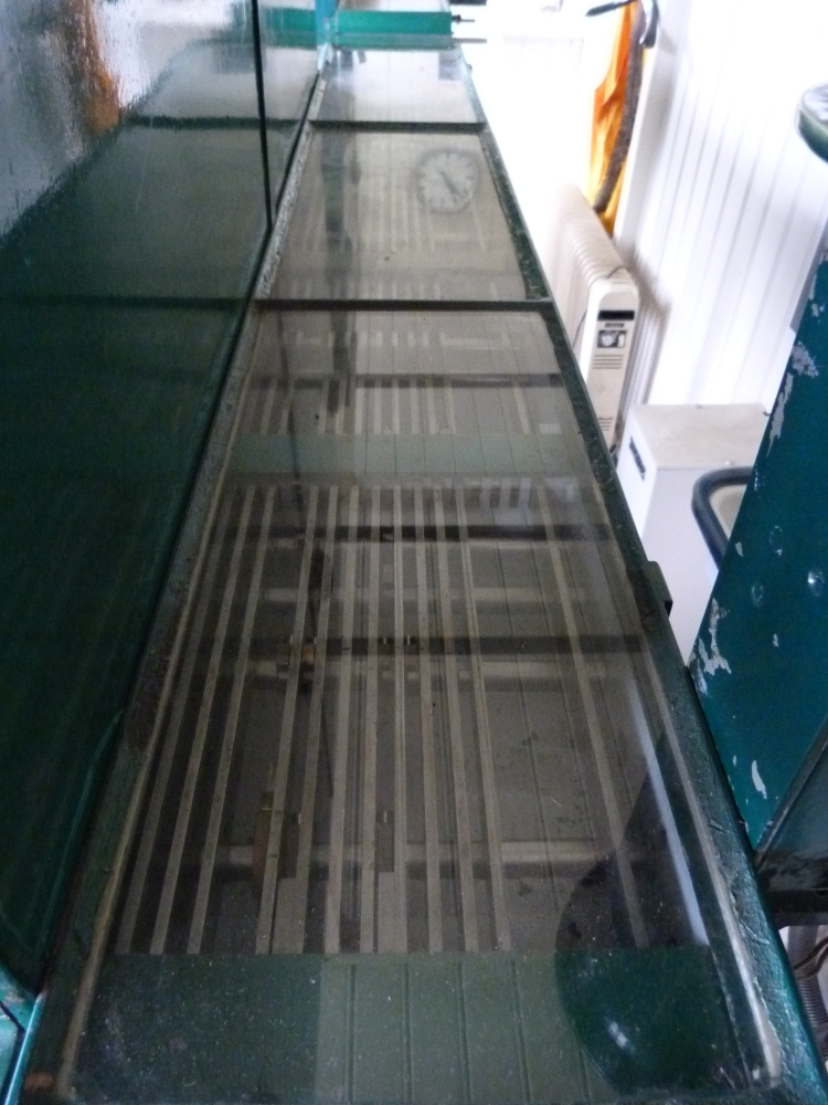
Locking bed, post I, Simpelveld, 16.8.2015
Under the glass, one can see a few details of the type 3414 locking rods. The rods to the front are probably route locking rods, which are locked by block instruments, whereas the rods on the back side are probably signal locking rods:
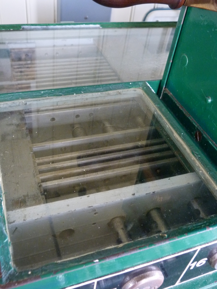
Locking bed, post I, Simpelveld, 16.8.2015
Here, one can see the locking fingers typical of Siemens's type 3414 (see also the first posting with drawings from Christian Hager's book on Austrian interlockings). On the rods, simple pegs are mounted, which prevent the movement of the locking elements formed like birds' tails that are mounted on the axles moved by the levers:
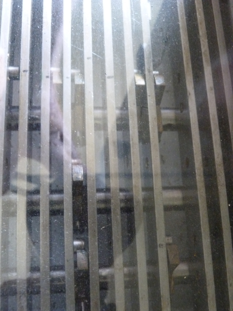
Locking bed, post I, Simpelveld, 16.8.2015
Locking bed, post I, Simpelveld, 16.8.2015
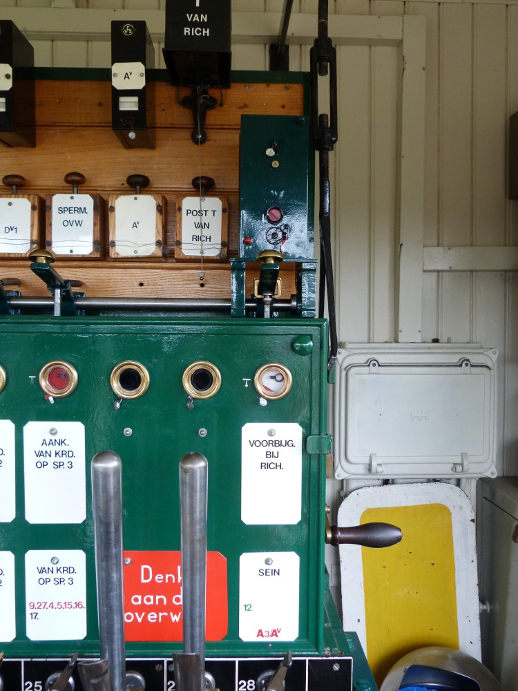
In this detail of the block instruments, one can see at left the signal locking instruments for the home signal from Kerkrade and on the right the block instrument of the line block from Bocholtz (formerly Richterich) with the button lock mounted above:
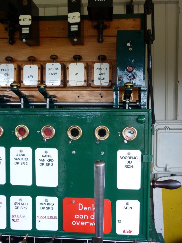
Block instruments, post I, Simpelveld, 16.8.2015
The following detail of the three signal locking block instruments for the three possible routes from Kerkrade into station tracks shows the "eye" in the anchor that is typical for German block instruments:
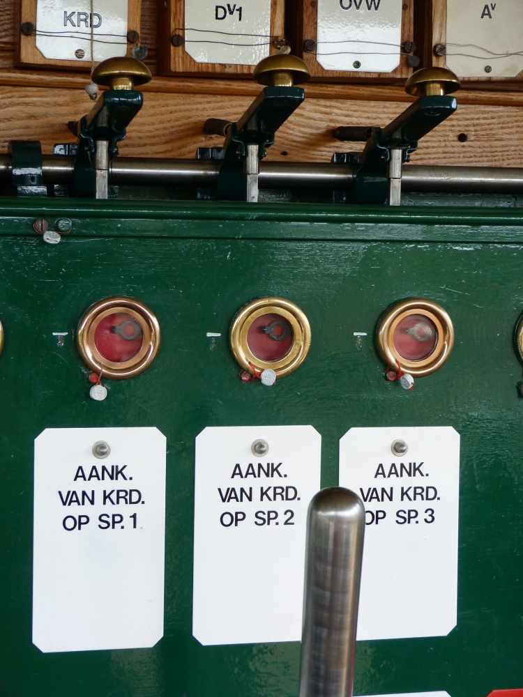
Block instruments, post I, Simpelveld, 16.8.2015
Near each instrument, there is a small white arrow showing whether the instrument is blocked or unblocked in normal position. If the arrow is below the horizontal line, as can be seen here, the instrument is normally blocked:
Line block instrument, post I, Simpelveld, 16.8.2015
Before I show a few pictures of a train run entering Simpelveld, here is an attempt to understand the station blocking. The instruments gave me a little bit of a headache because it seems that some instruments are missing from post I; and therefore, some of the instruments from post T are not connected. In principle, station blocking in the Netherlands works as follows (explained for a train entering a station):
- First, the signal man reverses the points and locks the routes with a small route lever.
- Using a block instrument marked "Van ...", the route is then locked electrically; a corresponding "Van ..." instrument in post T is unblocked at the same time (this is similar to the Ff and Fa instruments in Austria).
- In a next step, the treindienstleider (traffic director) unlocks the signal by blocking an instrument marked "Aank..."; a connected "Aank." instrument on the signal box's frame is thereby unblocked and unlocks the signal rod.
- Now, the signalman can clear the signal.
- The signalman returns the signal to "stop" and blocks his "Aank" instrument. This prevents the signal from being cleared (as in Austria, and different from Germany, there is no mechanism preventing that the signal can be cleared repeatedly while the "Aank" instrument is unblocked).
- The traindienstleider unblocks the route by blocking the "Van ..." instrument.
- The corresponding "Van ..." instrument at the signal box is unblocked, so that the route lever can be reset to normal, which in turn allows the levers of the points and shunting signals to move freely.
- In the Netherlands, in a first step the route is locked on the signal box, and then the signal block instrument is operated by the traffic director to unlock the signal, which no can be cleared by the signalman.
- In Austria, the first step is that the traffic director operates the signal block instrument, then the route is locked on the signal box, and now the signal can be cleared.
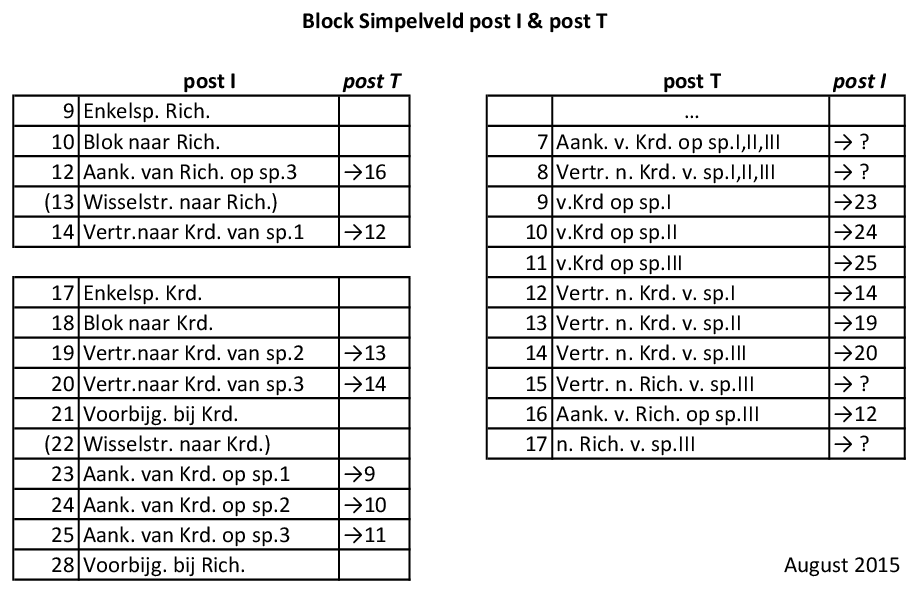
The following diagram shows the connections of the block instruments for post I in Simpelveld according to what I think. The order of the instruments at post T is show in reverse, to reduce the number of crossing lines. For a few instruments from post T, I have not found any corresponding instruments at post I; and it seems to me that the instruments for the second phase of the sequence above, where the traffic director unlocks a signal, are simply missing!

Here is a table view of the instruments and their connections:
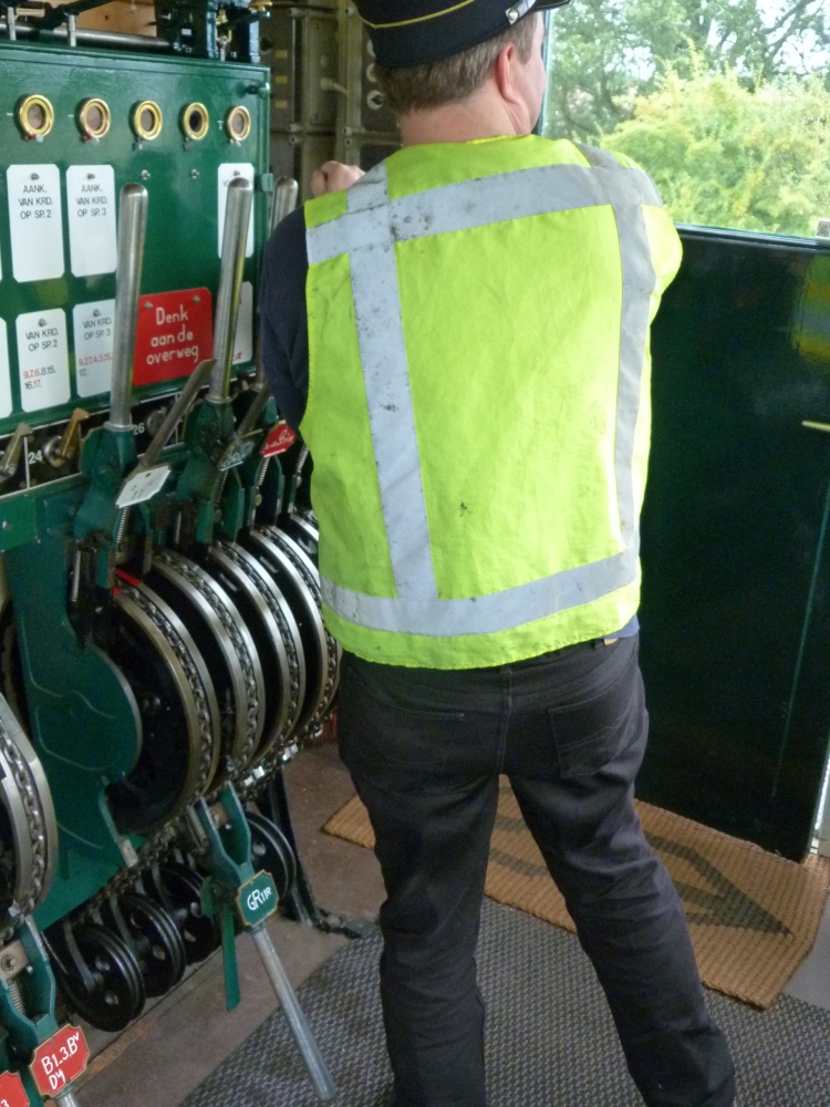
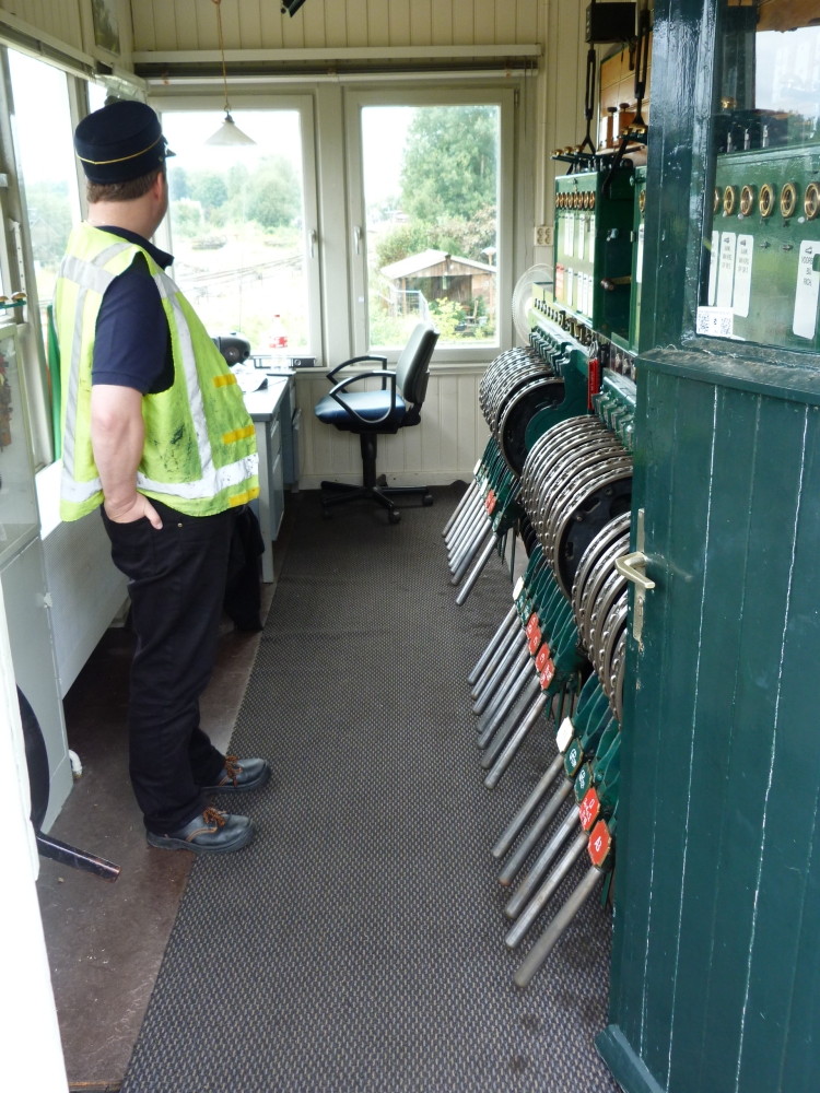
But now, let me return to pictures of the signal box. In the next one, the signalman watches the shunting moves outside:
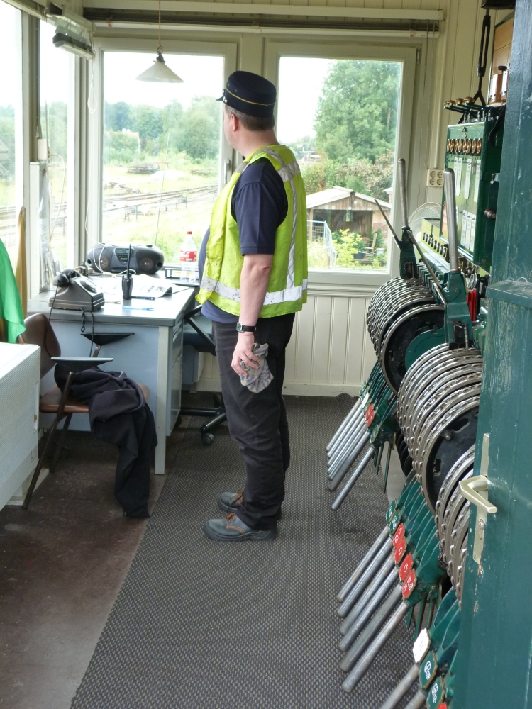
Signalman, post I, Simpelveld, 16.8.2015
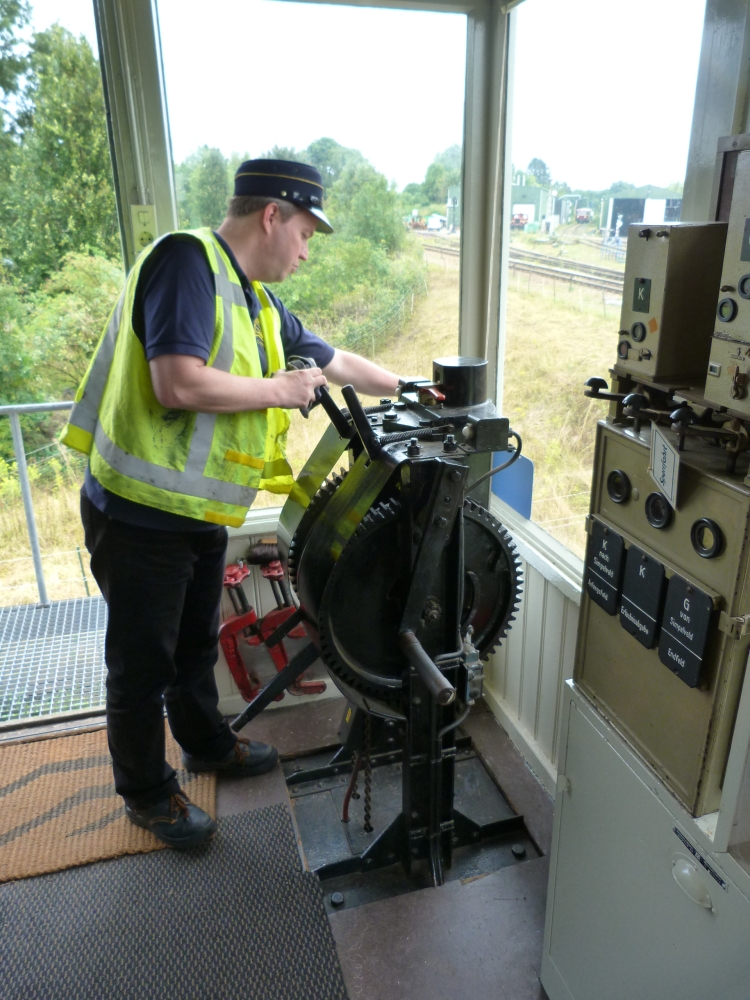
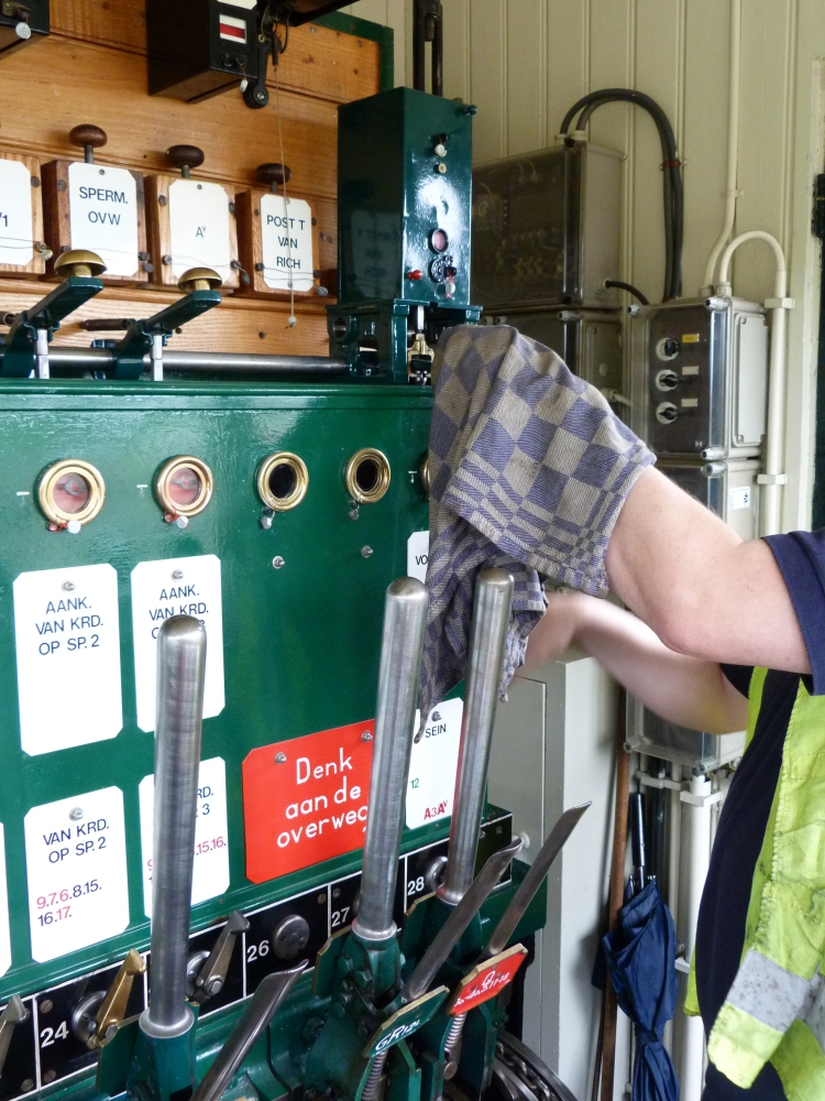
Before reversing a set of points, he takes—as is customary in Britain, but not in Germany and Austria, even for unpainted, shining steel handles—a piece of cloth ...
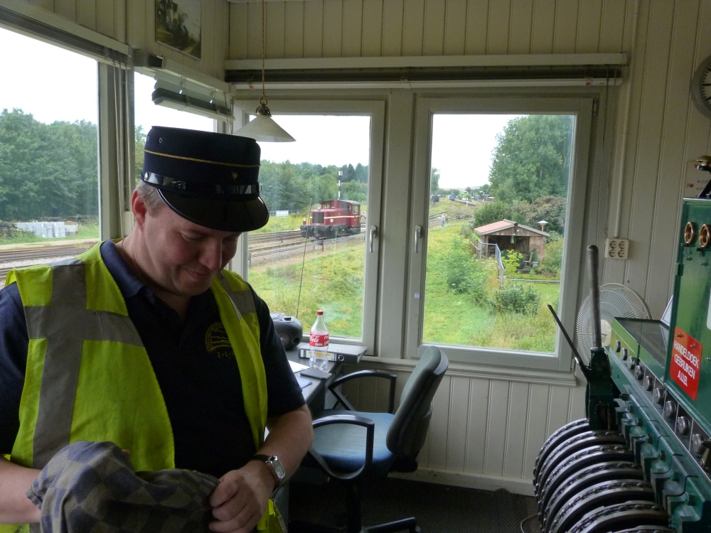
Signalman, post I, Simpelveld, 16.8.2015
... and uses it to grip the handle:
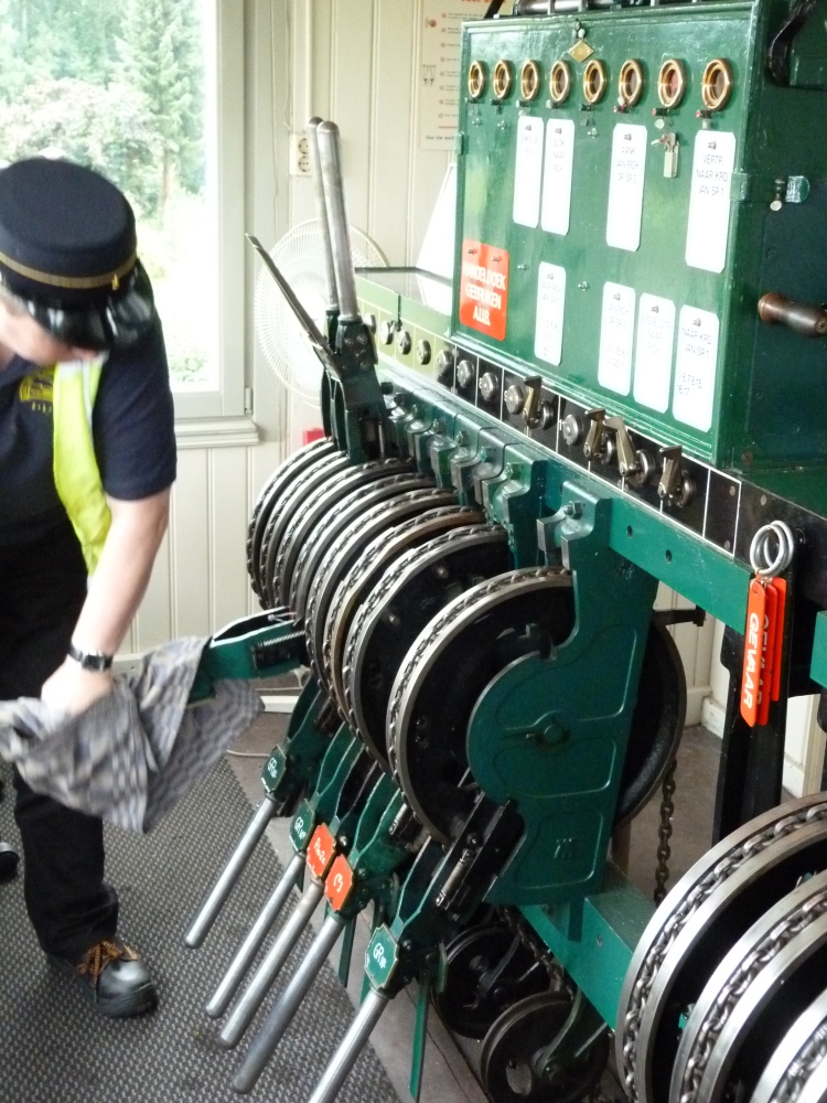
Reversing points, post I, Simpelveld, 16.8.2015
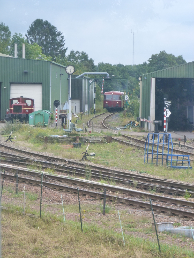
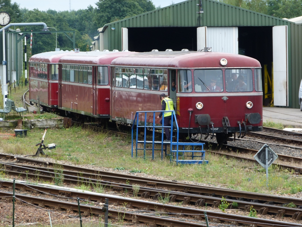
At the home signal from Bocholtz, the railcar is waiting:
Railcar is waiting outside station, Simpelveld, 16.8.2015
Below the clock, one can see the back of home signal A3, still showing stop:
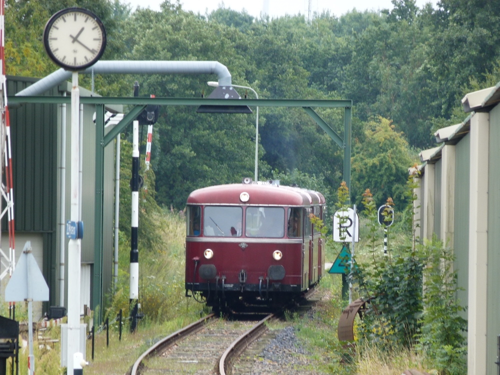
Railcar is waiting outside station, Simpelveld, 16.8.2015
The reason is that the shunting crew was a little slow with their job:
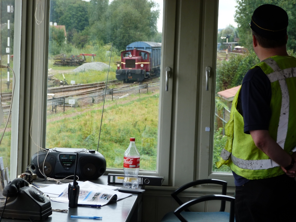
Shunting engine pulling cars, Simpelveld, 16.8.2015
After the shunting engine has moved to track 1 via the connection 13B-13A, the signalman could set the route for the railcar—however, the shunting crew forgot to reverse points 12B to their normal position. There is no help—the signalman must go out:
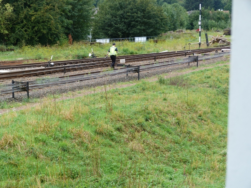
Points 12B need to be reversed, Simpelveld, 16.8.2015
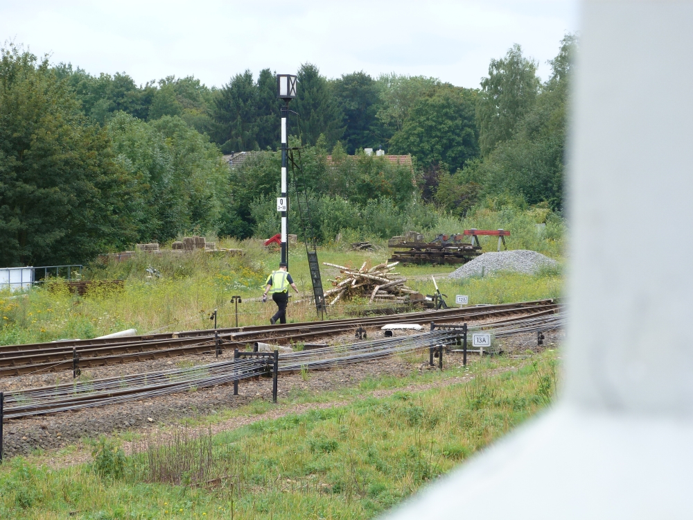
Points 12B need to be reversed, Simpelveld, 16.8.2015
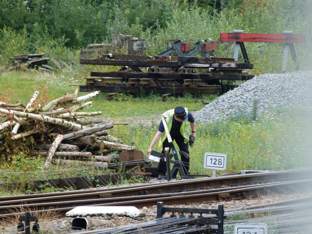
Reversing points 12B, Simpelveld, 16.8.2015

Reversing points 12B, Simpelveld, 16.8.2015
Now, the points are all lined up correctly, the route lever is reversed, and the block instrument for route locking can be operated:
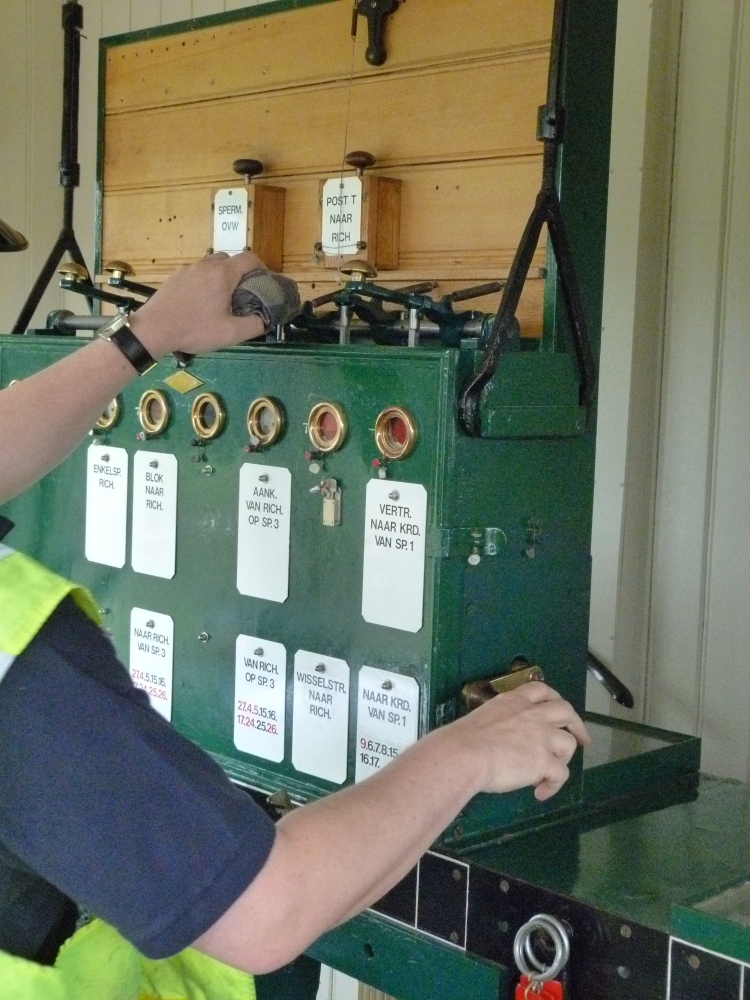
Blocking the route, post I, Simpelveld, 16.8.2015
Next, the barriers have to be lowered. Like in some British installations for gates, there is a separate crank for each barrier:
Closing the barriers, post I, Simpelveld, 16.8.2015
Closing the barriers, post I, Simpelveld, 16.8.2015
The train is still waiting, ...
Railcar is still waiting, Simpelveld, 16.8.2015
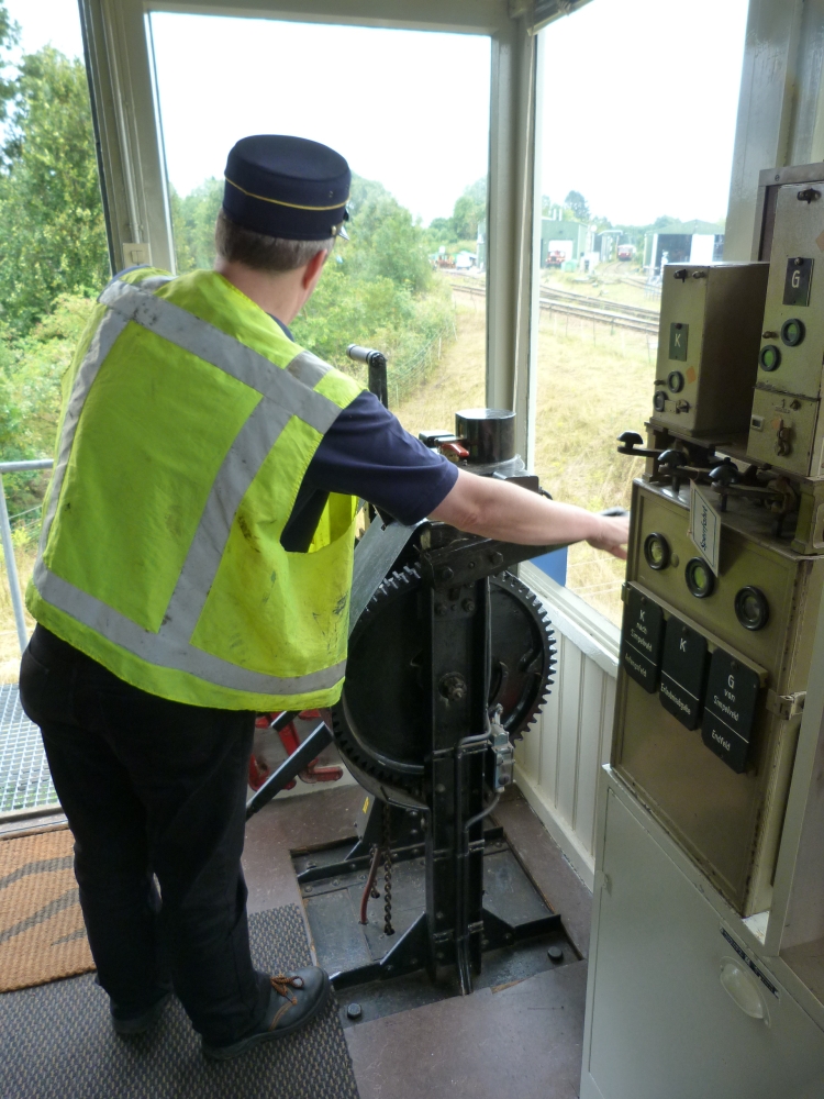
... but now the signal is cleared:
Clearing home signal A3, post I, Simpelveld, 16.8.2015
The train can now come into the station. Below the clock, one can see the inclined arm of home signal A3:
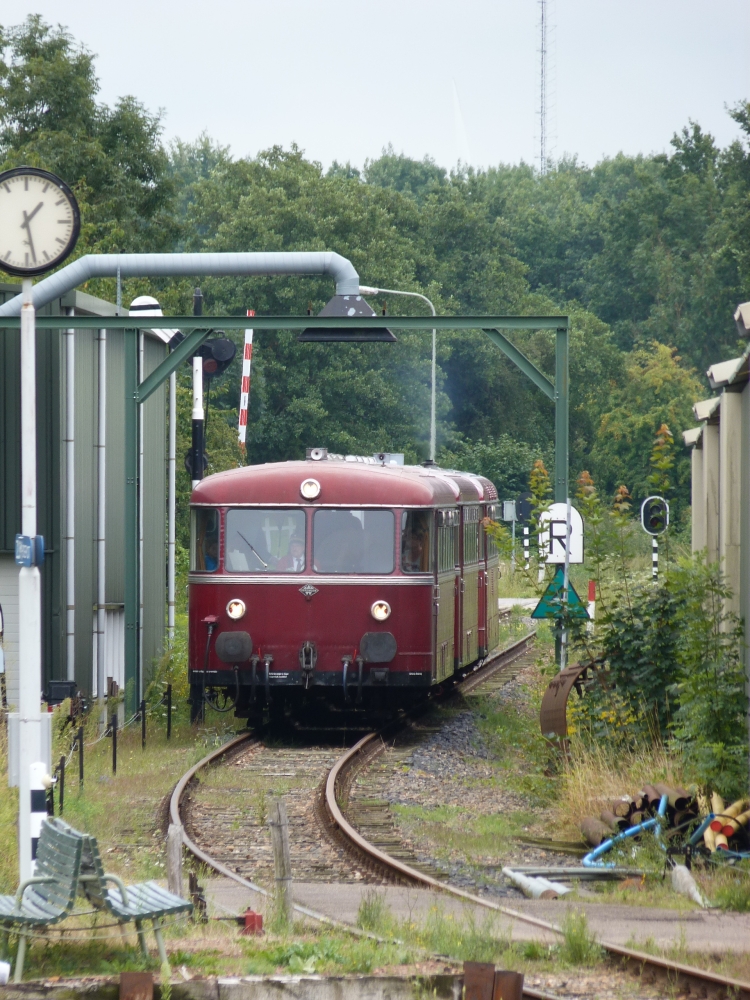
Railcar coming in (on the left, home signal A3), Simpelveld, 16.8.2015
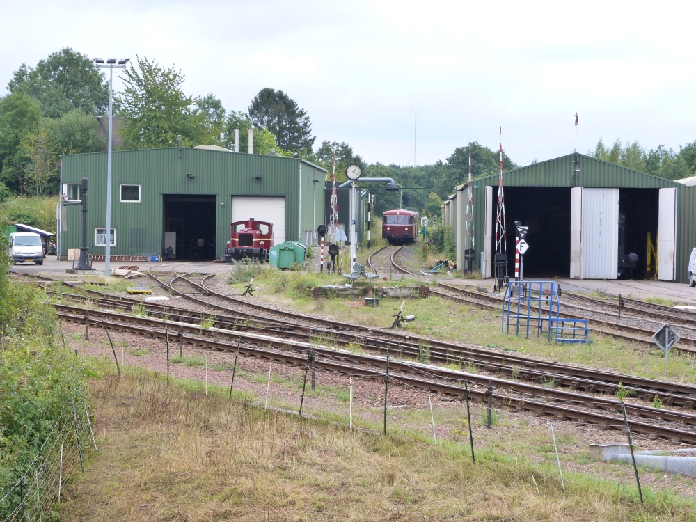
There is a short stop at the short platform near the locomotive shed:
Railcar stops at shed, Simpelveld, 16.8.2015
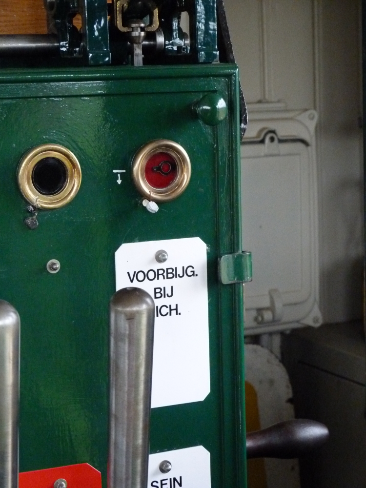
After the home signal has been returned to "stop," the line block instrument is "blocked back." Also here, the signalman uses the piece of cloth to avoid touching the bare metal:
Blocking the "Voorbijgang" instrument, post I, Simpelveld, 16.8.2015
Voorbijgang is blocked, post I, Simpelveld, 16.8.2015
And finally, here are two pictures of the frame showing all levers in their normal position:
Lever frame in normal position, post I, Simpelveld, 16.8.2015
Lever frame in normal position, post I, Simpelveld, 16.8.2015
No comments:
Post a Comment