Update 22.12.2019: My explanations of these tensioners were wrong until yesterday. Now they are correct (or at least plausible).
Rapolano Terme is a small station near Asciano in Tuscany, where the tracks towards Sinalunga run in a wide loop around the small town at the top of a hill. There were only a handful of signals—but they were situated quite strangely: There were two home signals—but two more signals protected two road crossings, and one of these sort of doubled as a starting signal of the station. The home signals were operated from the station, but the two protecting signals were operated from the post at one of the crossings. Additionally, new colour light signals and electric points motors had been installed, but these were not yet connected. The following pictures show the old mechanical signalling devices in and around the station.
Below, there is a diagram of the tracks, together with the signals and the location of the few levers. I took photos of only one semaphore, marked 2 in the diagram and show with a solid signal post. The other three signals, whose position I can only guess, are shown with a dashed post.
- First, there is the home signal from Asciano, marked with 1.
- The home signal on the other side had no mark on its lever—I use an asterisk for it.
- A last, protecting signal must have been far away from the crossing post, which is also marked with 1, because its lever had this number.
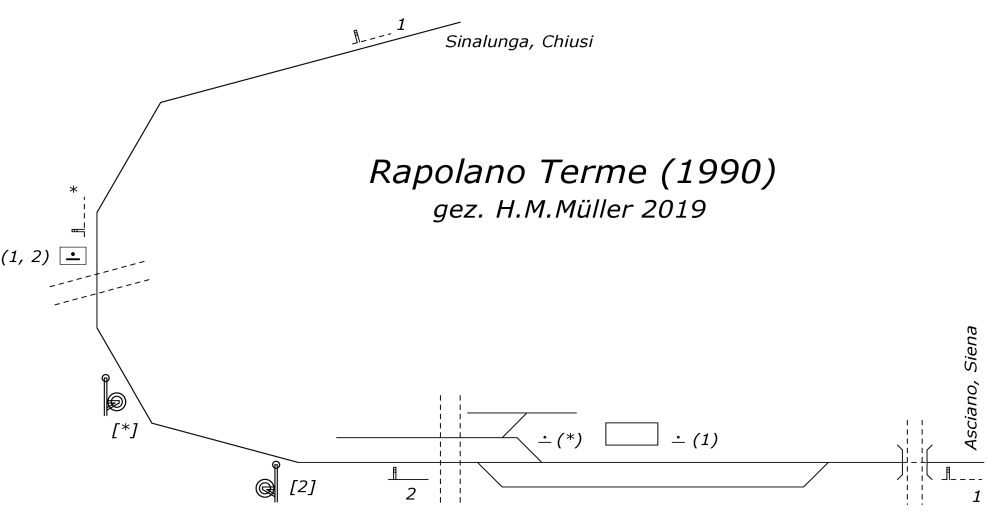
Track and signal plan of Rapolano Terme in 1990
Let us now take a closer look at all these items.
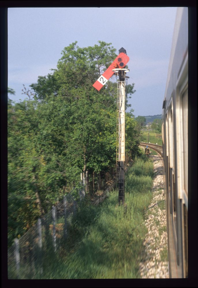
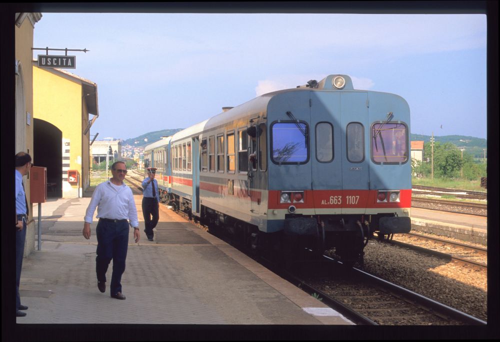
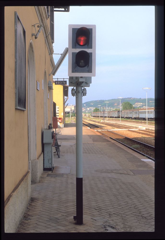
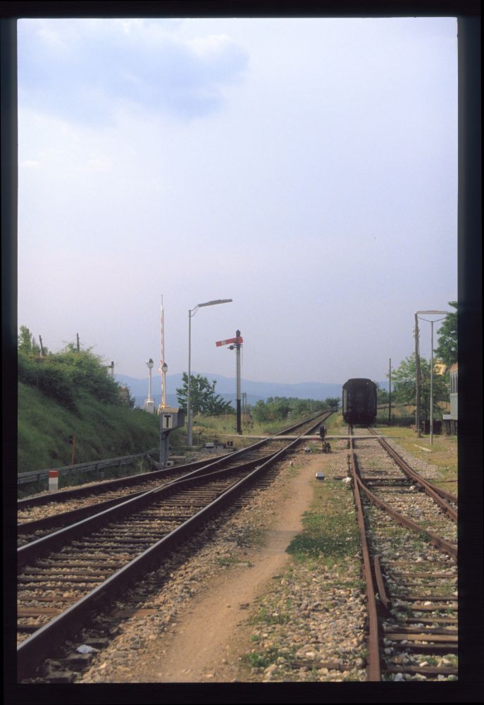
In the first photo, we see how our diesel railcar leaves the station, heading for Sinalunga. At the left, the new signal gantry holds two starting signals. In the background, protecting signal 2 is still cleared:
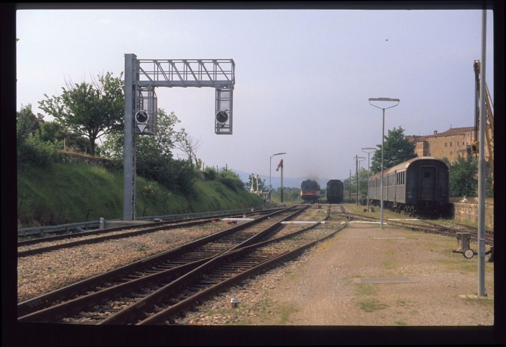
Departure of an Aln663, new starting signals and a semaphore protecting signal, Rapolano Terme, May 1990
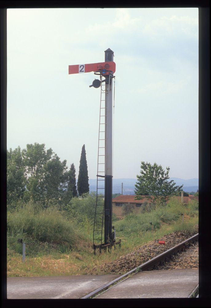
For a long time after the departure, the semaphore remains cleared. A starting signal would have been returned shortly afterwards—so, this alone indicates that this signal is not operated from the station, but from somewhere else. Also, there is no lever in the station for it. Thus, I argue that this is protecting signal for some railway crossings, necessary because the town on the hill hides the crossings, and a train might leave the station when the barriers are still lifted:
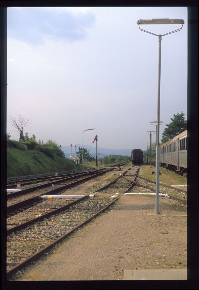
Semaphore is still cleared, Rapolano Terme, May 1990
Some time later, the semaphore arm returns—the train has, most probably, now passed the barriers or at least the post operating them:
Semaphore arm returns, Rapolano Terme, May 1990
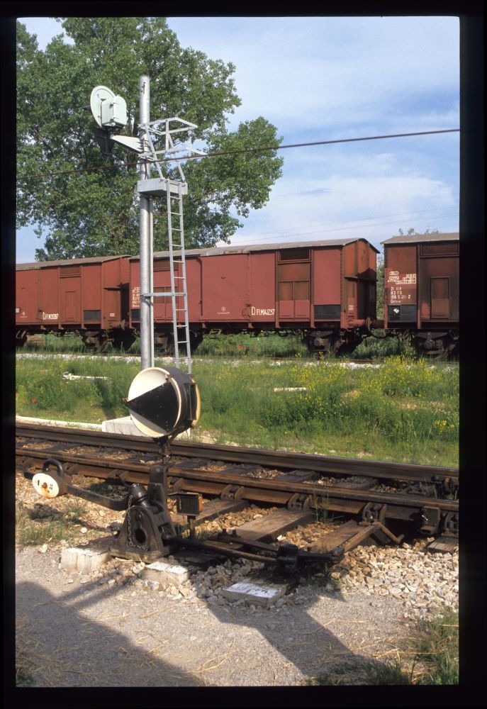
Semaphore, Rapolano Terme, May 1990
Here is the signal arm on the protecting signal. As in Britain, and in contrast to Central Europe. Italian semaphores are operated with a single wire:
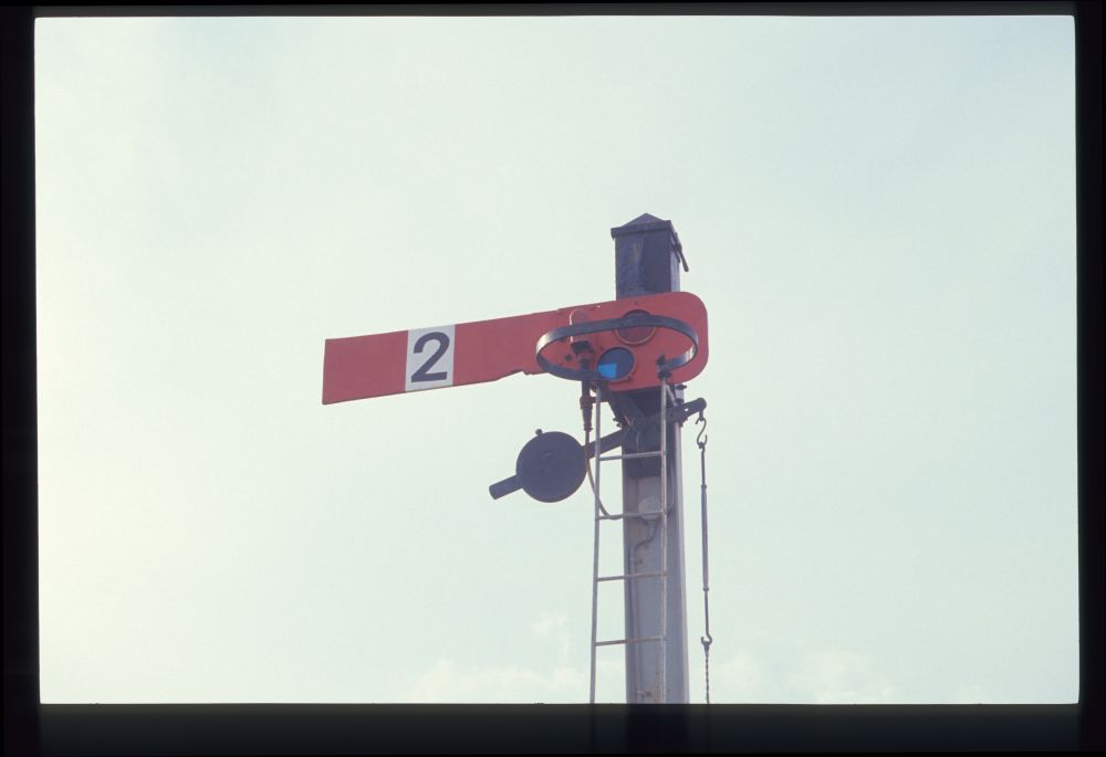
Semaphore, Rapolano Terme, May 1990
A photo above shows the new signals. In the following photo, we see a new points machine for future remote control of the station. The motor has been bolted to the points, but the four bars for moving and locking the blades are still missing:
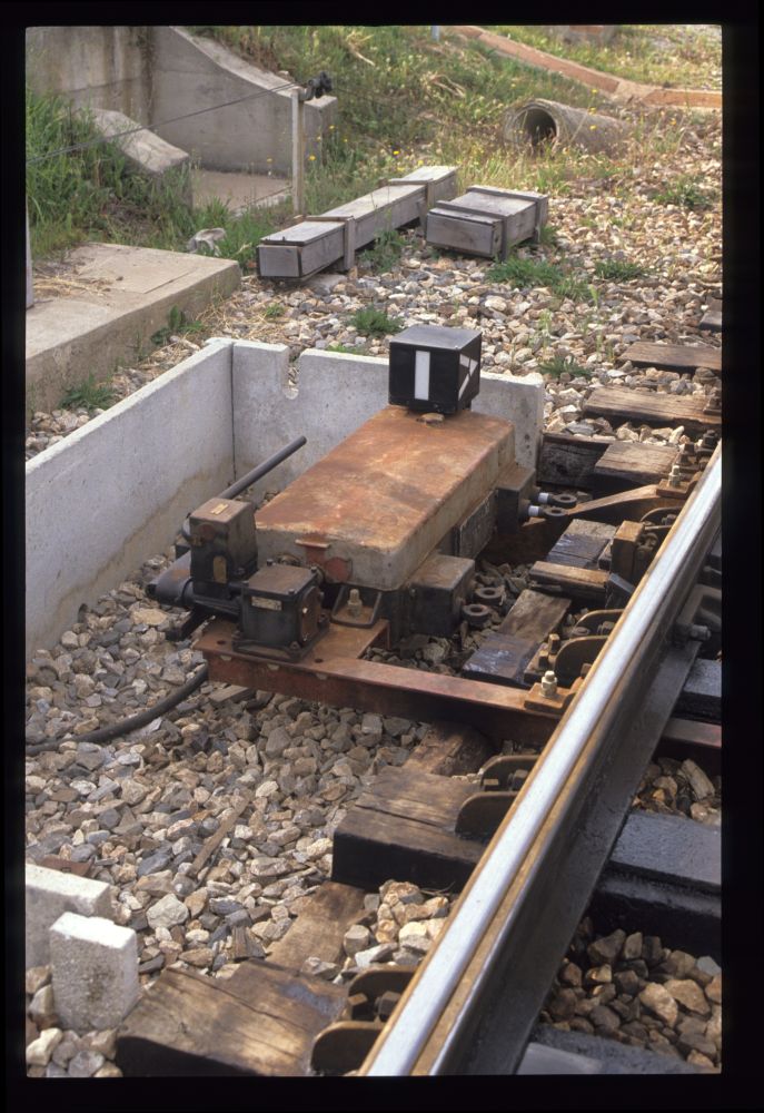
New points machine without bars, Rapolano Terme, May 1990
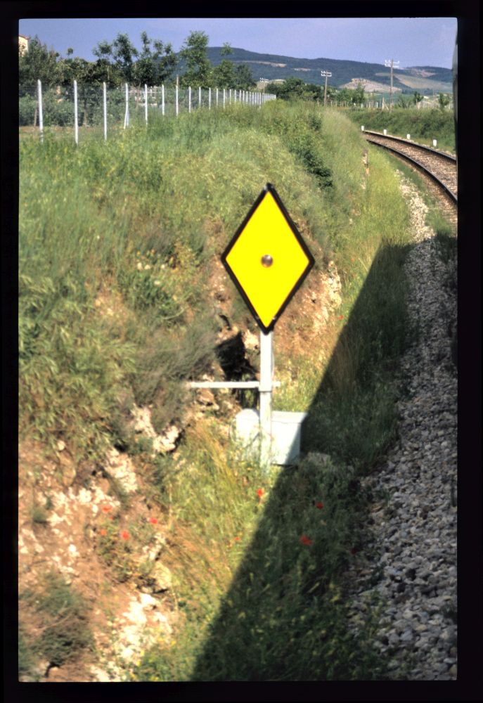
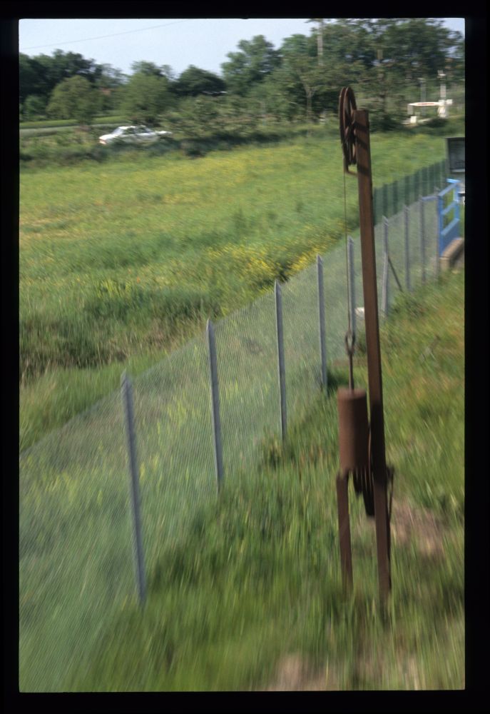
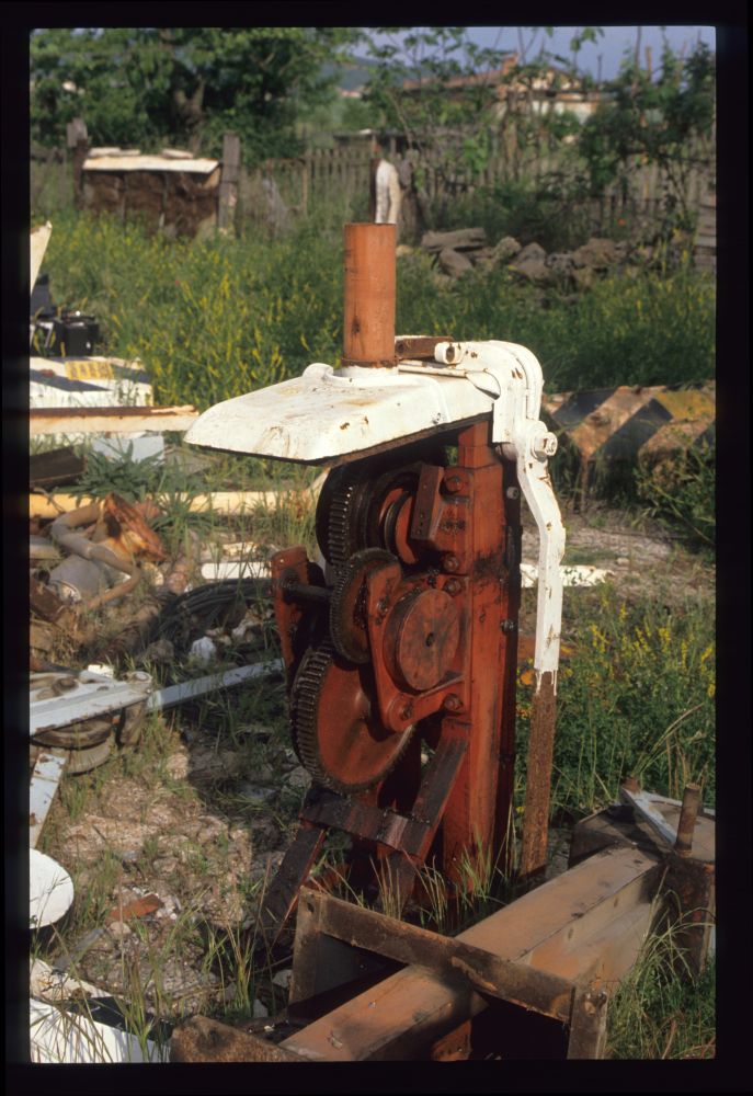
At the barriers located near the semaphore, one can see the old driving gear and, additionally, the new one with flashing lights, but without red dots on the star wheel:
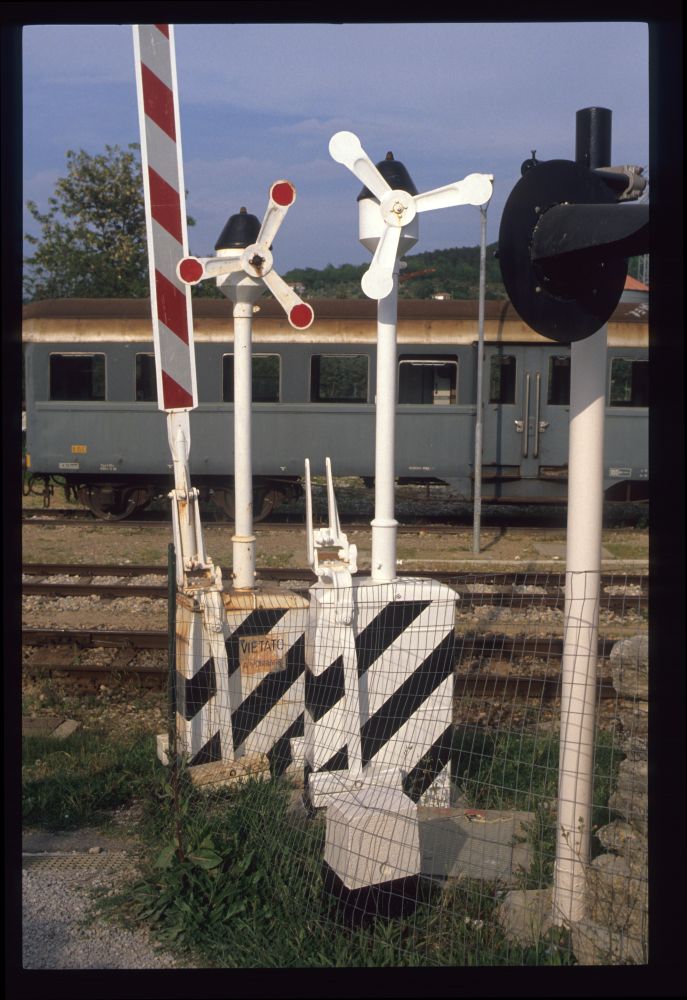
Old and new barrier drive, Rapolano Terme, May 1990
I then returned to the station, taking a photo of an old crane at the last track. For some reason, the film was completely clear in its lower section, which I tried to cover with a black piece of film. However, during or before scanning, that black piece moved upwards and ... well. The crane, by the way, is still standing at Rapolano Terme, as one can see on various satellite images and on Google Street View, when turning from the crossing towards the station. It is now far away from the nearest track and completely useless, and why it was not removed, is completely unclear:
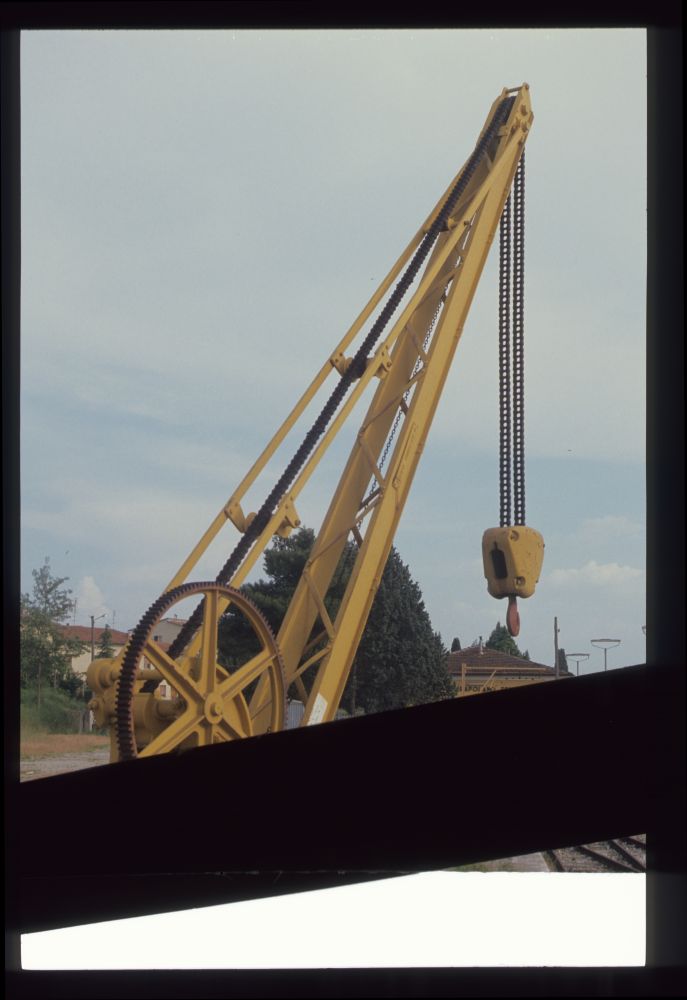
Old crane, Rapolano Terme, May 1990
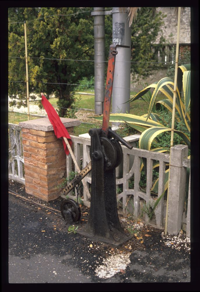
But let's return to signalling equipment. The following picture shows the crank for the barriers on the left, on the right is the lever for the home signal from Sinalunga. The lever is locked here with a locking piece connected with a chain to the counterweight lever. And one can see that the signal is cleared by releasing the wire—quite a dangerous practice, isn't it? After all, when the wire breaks, the signal will be cleared just so! We will see below that problem is not that large, but still ... Above the crank for the barrier, one can see two red rings indicating that the barriers are raised:
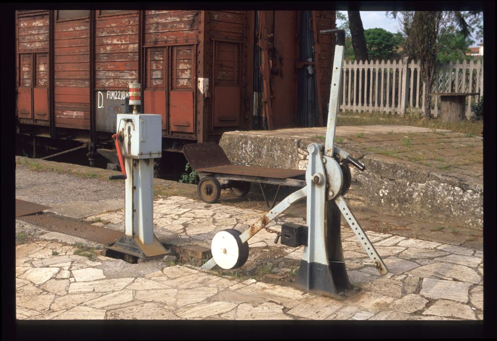
Barriers and home signal lever from Sinalunga, Rapolano Terme, May 1990
This is the same lever, photographed from the back side:
Home signal lever from Sinalunga, Rapolano Terme, May 1990
For comparison, here is the home signal lever at Albano Laziale, which pulls at the wire for clearing the signal, like typical British levers. One can see that the distance from the wire's connection to the lever at Albano is about half that of the lever length at Rapolano—thus, there must be a reduction of the wire travel by 2:1 somewhere (if one assumes that all semaphores needed the same wire travel for clearing the arm):
Signal lever, Albano Laziale, May 1990
Of course, I wanted to understand how the signal was really cleared. After all, the signal arm definitely must be pulled down. How does a released signal wire do that? So I started marching along the tracks ...
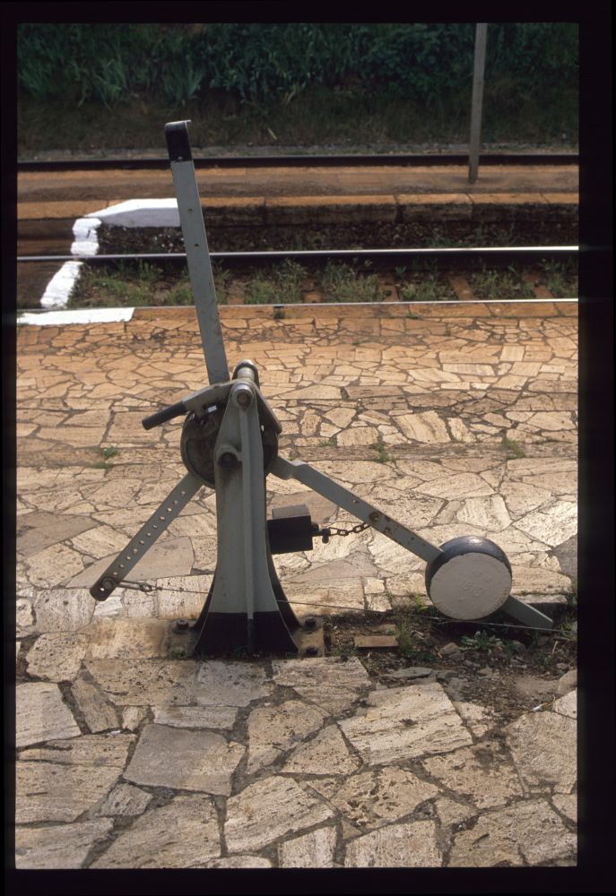
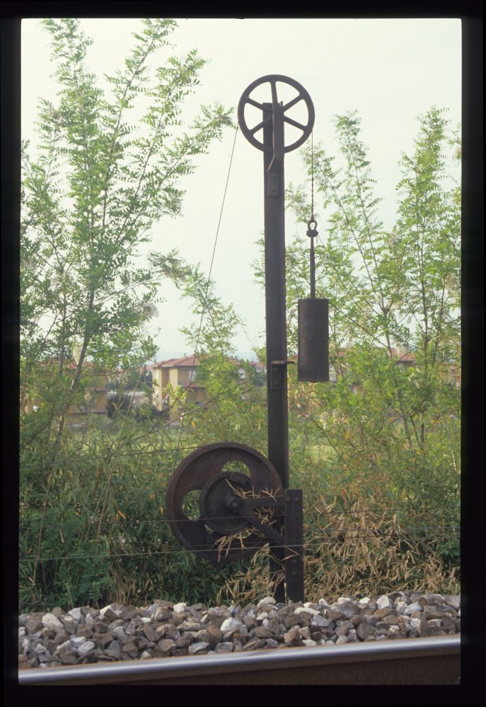
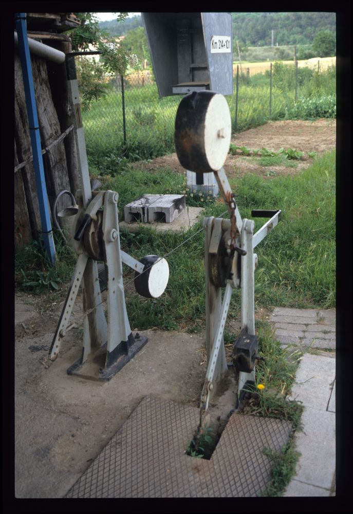
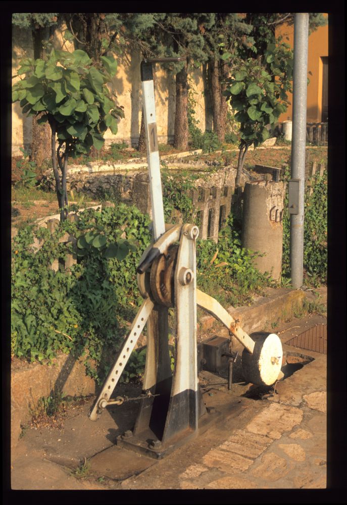
On my way, I encountered the following tensioner. I do not know a description of its function, but I think it can be derived without too much difficulty from its simple construction:
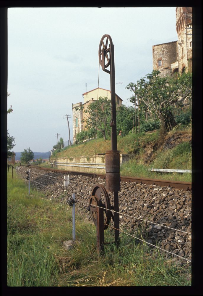
Tensioner for "starting signal", Rapolano Terme, May 1990
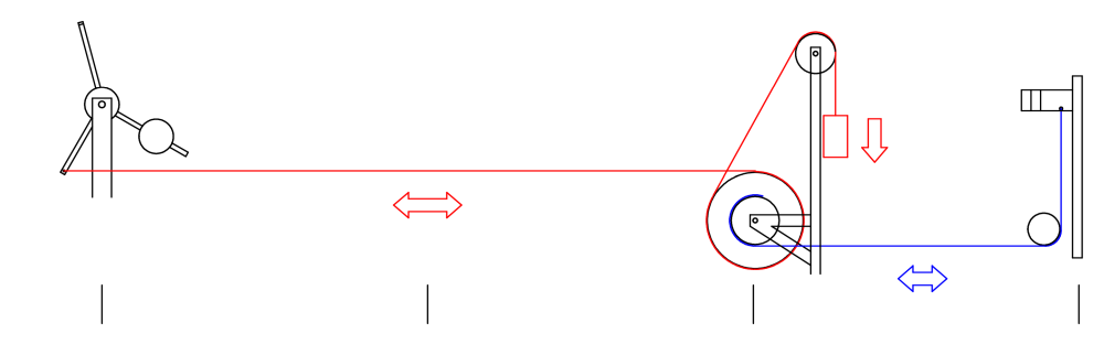
I have tried to create a small diagram showing how the tensioner is placed between the signal lever (on the left) and the signal (on the right). By pulling the lever, the (red) wire is released. At the tensioner, the double wheel can now turn clockwise, which is done by the heavy red weight, which therefore pulls at the blue wire and clears the signal by pulling down the signal arm:
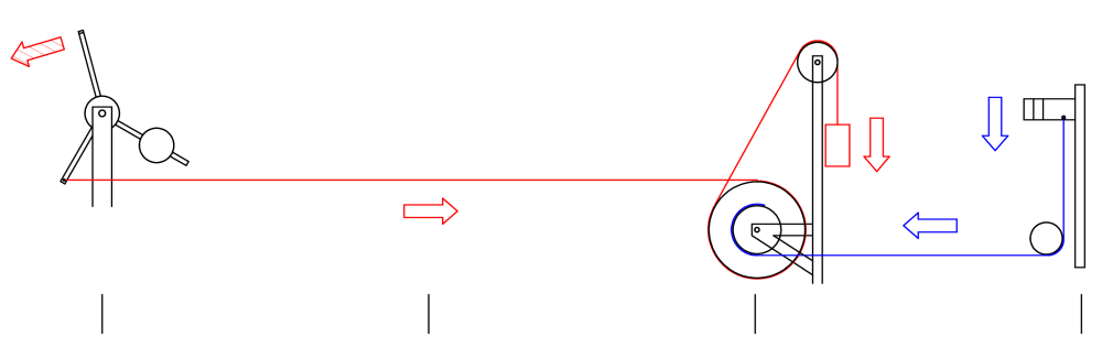
When the lever is returned to normal, the weight at the tensioner is lifted, and the blue wire is released so that the signal arm can return to its horizontal position. The counterweight at the signal lever helps with the lifting of the tensioner's weight.
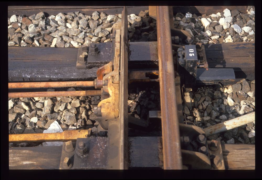
Here is a closeup of the double wheel. On the upper left, one can see the wire coming from the lever, whereas the wire on the right goes to the signal. The almost vertical wire is connected to the weight. The wire in front of the tensioner comes from the lever at the station and continues to another tensioner we will see in a moment:
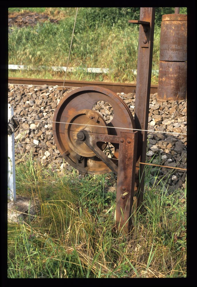
Tensioner, Rapolano Terme, May 1990
Actually, the red wire consists of two pieces. The following enlargement shows that the wire coming from the lever is connected to a special hook. This hook will be released if the wire breaks, and by some mechanism will prevent the wheel from turning so that the signal does not get cleared. However, I do not know how this works in detail, and it is hard to reconstruct it from this single photo:
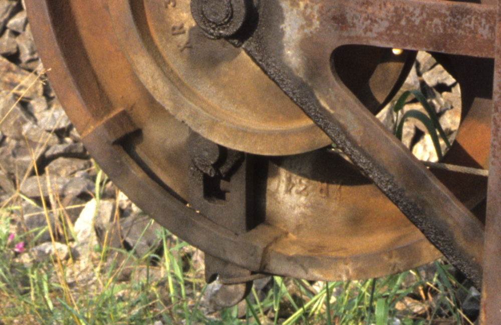
Tensioner, Rapolano Terme, May 1990
Because of the opposing movement of the wires from the lever and to the signal, the tensioner also works as a compensator if it is placed at the right distance from the lever. The pictures show that the two connected wheels have a diameter ratio of about 1:2. Thus, if the tensioner is placed at about a third of the distance from the signal, this will allow it to compensate uniform expansions or contractions of the wires by temperature changes quite nicely:
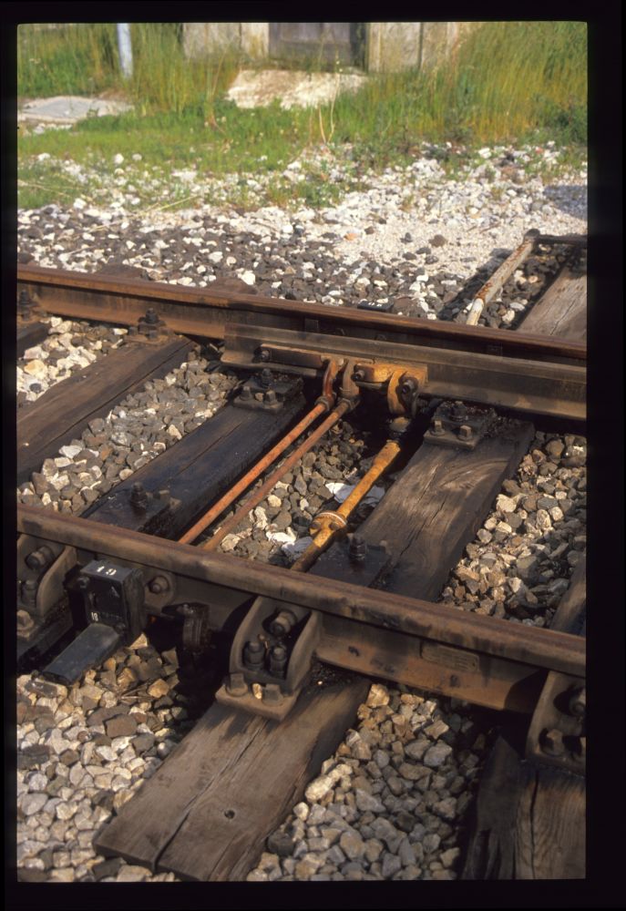
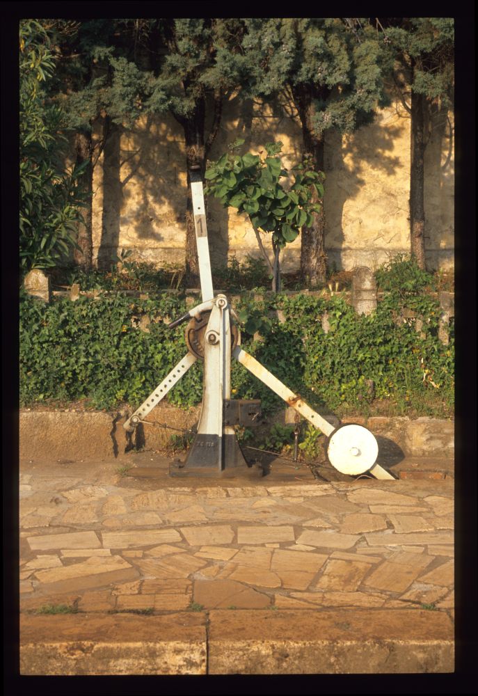
Continuing on my way along the wide track curve around the hill of Rapolano Terme, I encountered another tensioner. This one is for the home signal farther down the road:
Tensioner, Rapolano Terme, May 1990
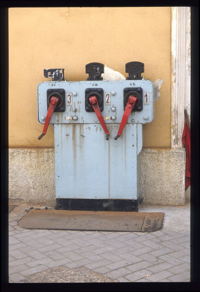
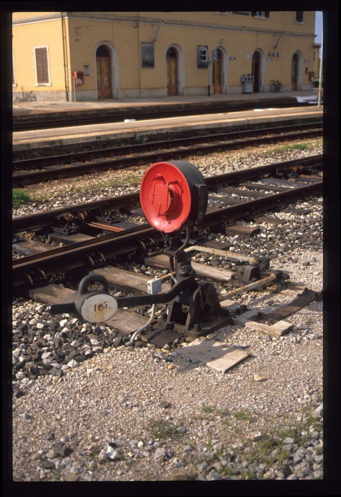
Finally, at km 214.101, I reached a small post that operated two barriers—and two signals! On top of both barrier cranks, one can see white rings, so the barriers are closed, and a train is expected:
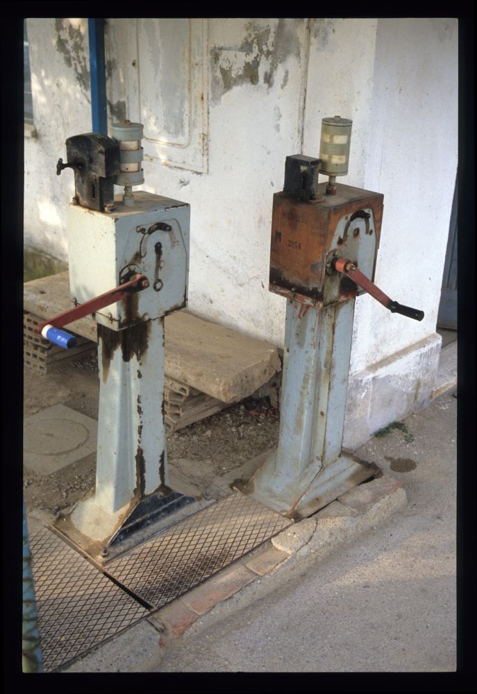
Barrier cranks at post, Rapolano Terme, May 1990
Near the barrier cranks, there were two signal levers. The left one, numbered 1, was connected to a protecting signal on the Sinalunga side—here, the lever is in normal position so that the signal shows stop. The right lever, with number 2, is connected to the signal at the station, and it is reversed, i.e., the signal is cleared—a train is coming!
Signal levers at post, Rapolano Terme, May 1990
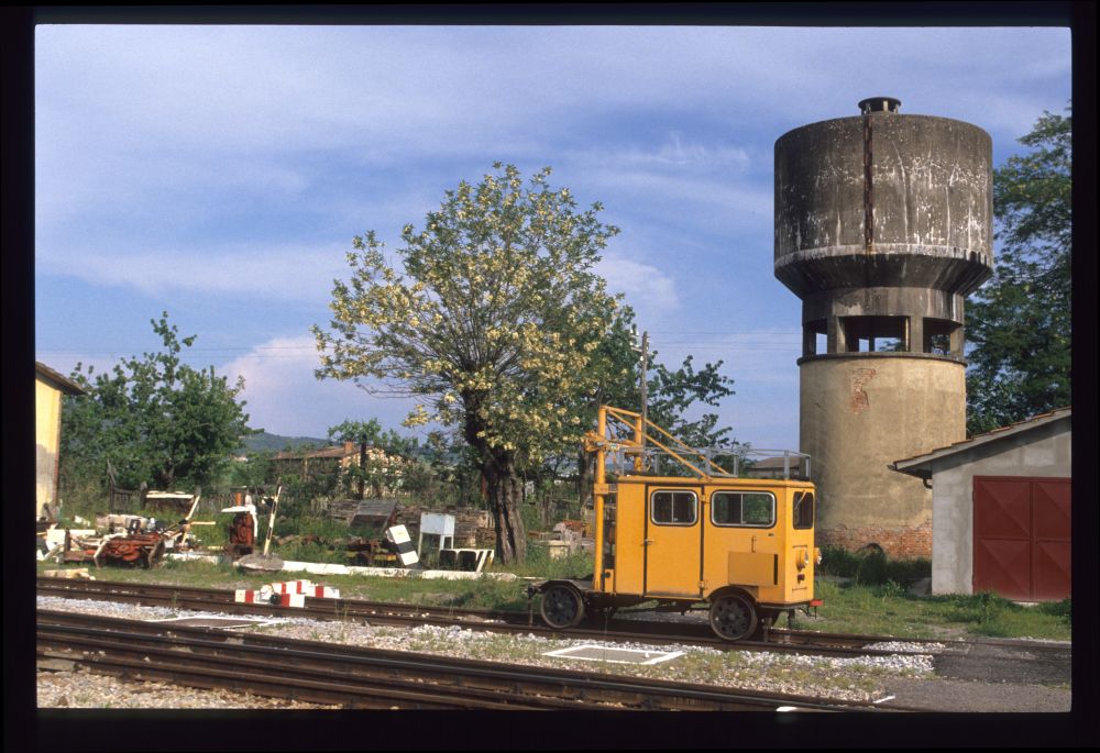
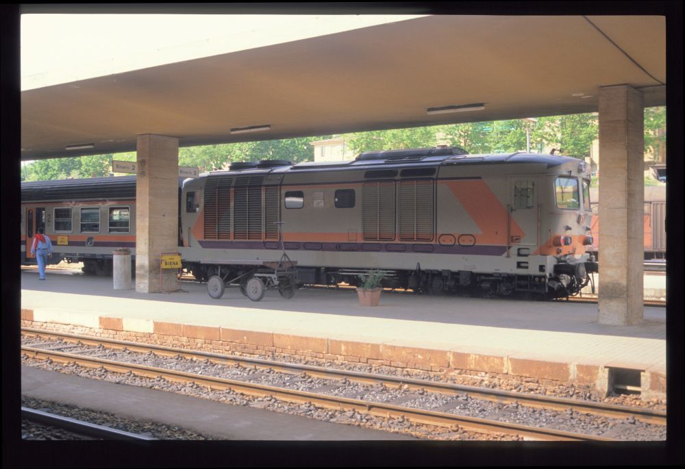
And here it is—the railcar is rolling down from the station towards the post on its way to Sinalunga:
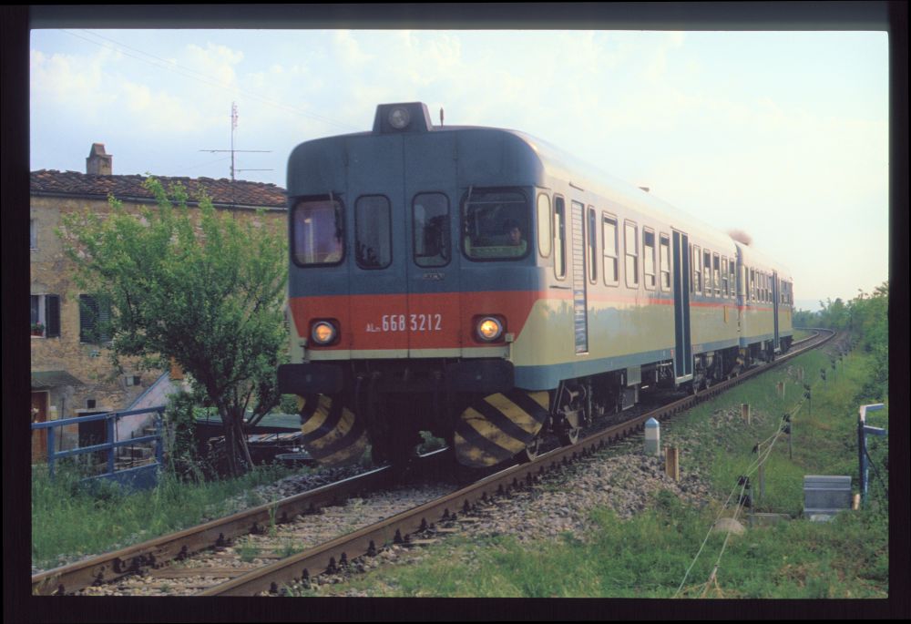
Aln668 3212, Rapolano Terme, May 1990
Unfortunately, I did not continue to the home signal, which must have been just a short distance behind the post—but I was not sure that I would reach our train back ...
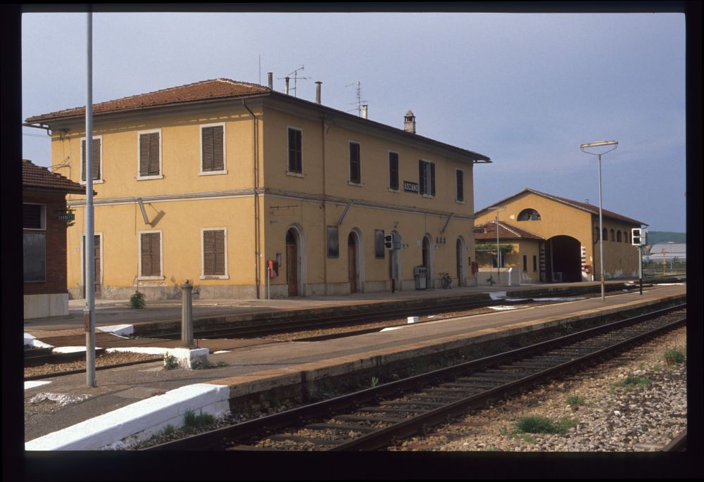
After arriving at the station once more, I took this picture of the station building, with a few goods cars visible in the background (I ignored all the old rolling stock set up on these tracks, most probably to be scrapped soon):
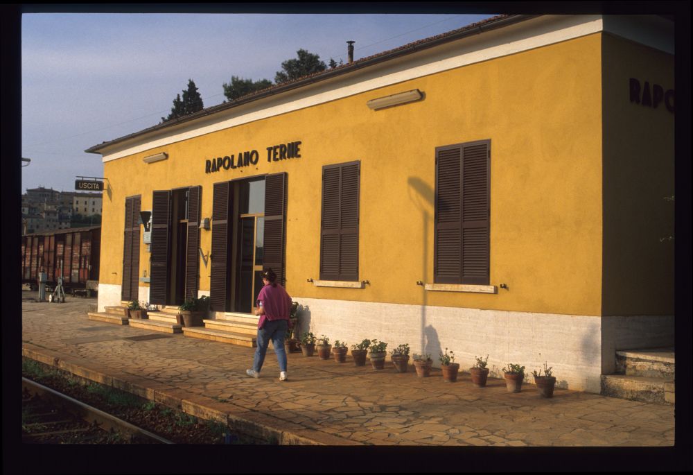
Station building, Rapolano Terme, May 1990
Here is the fourth signal lever, which operates the home signal from Asciano:
Home signal lever 1 from Asciano, Rapolano Terme, May 1990
Home signal lever 1 from Asciano, Rapolano Terme, May 1990
Not really a signalling equipment photo—but far away in the distance, one can see the overpass and the dark new starting signals:
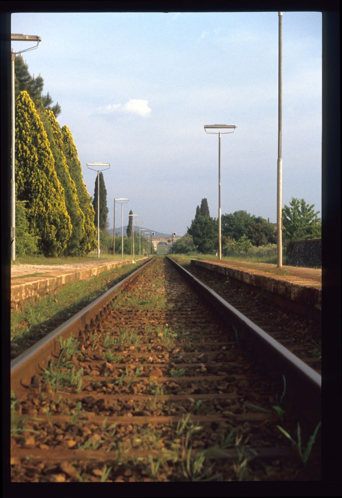
Track towards Asciano, Rapolano Terme, May 1990
Here is, again, the crank for the barriers near the protecting signal. The rings are now white, which means that the barriers are lowered and another train is due:
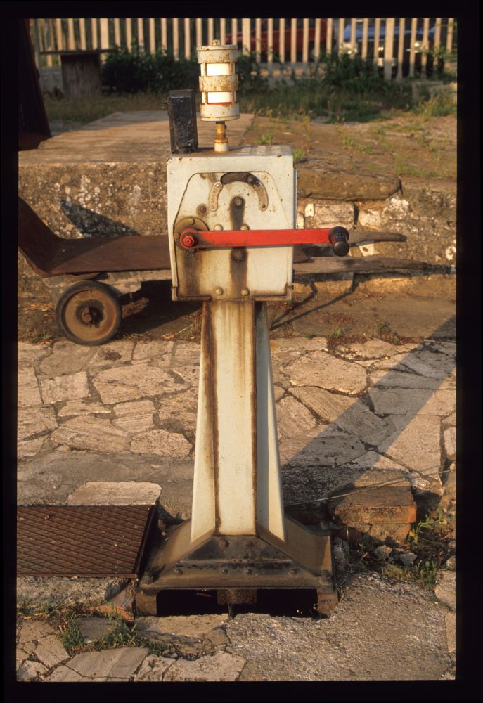
Barrier crank, Rapolano Terme, May 1990
And here is the final photo, of the signal lever from Sinalunga: Our train is approaching and will bring us back to Siena. However, there are no more photos from this trip:
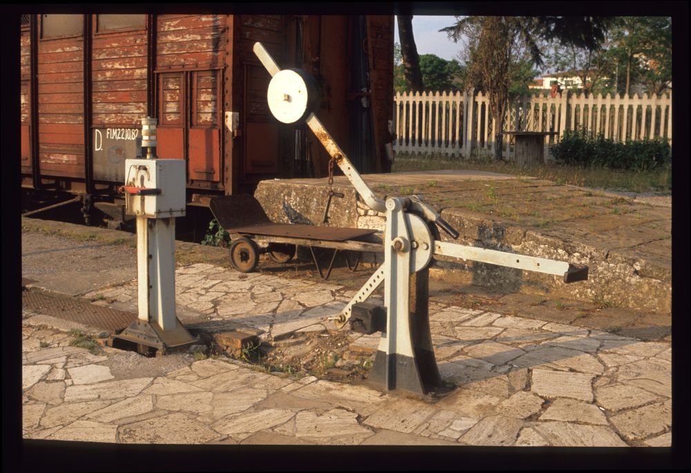
Barrier crank and home signal lever from Sinalunga, Rapolano Terme, May 1990