Sunday, March 10, 2013

My Austrian type 12SA lever frame: Exclusions between routes

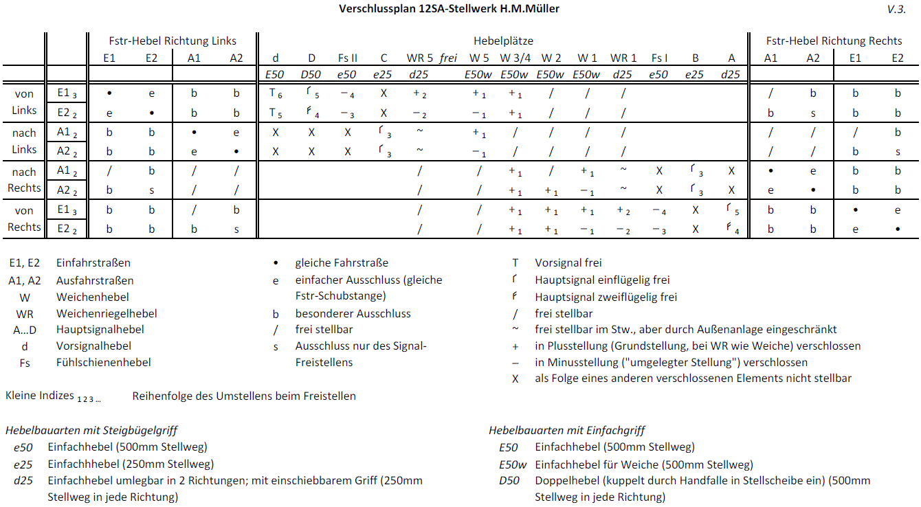
The locking table shows that many routes exclude each other. There are only a few pairs of routes that are possible at the same time:
  • Li-E1 and Re-A1 (through-train on main track no.1 from left to right)
  • Re-E1 and Li-A1 (through-train on main track no.1 from right to left)
  • Li-A1 and Re-A2; or Li-A2 and Re-A1 (leaving from different tracks into different directions after a meet)
and also (even though it is probably useless in practice, but poses no risk)
  • Li-A1 and Re-A1; or Li-A2 and Re-A2 (leaving from the same track into different directions)
All other exclusions are accomplished by one of the following three possibilities:
(a) simple exclusion, when two incompatible routes are on the same route bar;
(b) special exclusion, where a custom-purpose mechanical lock prevents locking two incompatible routes;
(c) as a special case, this 12SA allows some pairs of routes to be locked, but it is not possible to clear both signals! (This is done for the routes E2 and A2 on both sides.)

In principle, there is a fourth possibility:
(d) Two routes are incompatible when a route element (usually points) is not in the same position for both routes. In this station, this criterion would prevent the pairs E1+E2 and A1+A2 on both sides. However, these pairs are already excluded because of (a)!

Why did the designers of the 12SA not place entry and exit route for one track on the same route bar, i.e., use criterion (d)? After all, this would have saved this special mechanical exclusions for case (b) above! In many other types of interlocking, like the Austrian standard type 5007, but also the Austrian electro-mechanical types 42733 and EM55, this was done quite often. But there is a problem with this assignment of routes to route bars: If two routes behind a single signal (e.g. a home signal!) are placed on different route bars, this requires the mechanical equivalent of a logical "or". After all, the signal lever must be free to move if one or the other route bar has moved from its normal position. Examples of such "mechanical ors" are the "neutral bar" (Neutralschieber) of the 5007 or "group locks" ("Gruppenverschluss") and "group drive" ("Gruppenantrieb") of the German "Einheits-Type". However, such a "mechanical or" is a tricky element; and not at all advisable for the rugged type 12SA, which was usually located on the platform, where it had to cope with snow and ice and rain. Therefore, putting routes behind one signal on the same route bar and using additional devices for special exclusion actually simplified the locking apparatus!

Let us take a closer look at these special exclusions: My lever frame has three of them, of two different types. One of them lurked at the bottom of a picture shown in the posting about locking points levers:


Then the route bar is shifted left or right, the exclusion turns by about 45 degrees:


Seen from below:


The route bars whose movement is to be prevent contain stops, which cannot move when the hooks of the exclusion point upwards. The following picture (which shows the other exclusion of this form) shows such a stop:


The pairs of excluded routes are defined by placing the stops at different locations on the route bars.

The third special exclusion device (which prevents opposing movements) is built differently: The second route bar turns a locking disc via a pin:


The disc lies in front of the front route bar:


When it is turned, a notch on the disc and a corresponding pin on the route bar prevent the movement of the bar:


When, on the other hand, the front route bar has moved left or right, the pin locks the disc in place so that it cannot be turned by the second route bar:


Obviously, this type of special exclusion device fulfills its job like the one explained previously.

Our list of locking concepts has again grown by one entry:

a. Locking pin against locking weight lever (for points lever) or locking bar (for FPL lever)
b. Position check against chain wheel (for points lever)
c. Locking pin hook against chain wheel (for FPL lever)
d. Catches holding nose on chain wheel (for home signal levers)
e. Special exclusion device between route bars

Tuesday, March 5, 2013

My Austrian type 12SA lever frame: Locking the signal levers

Also route levers and signal levers must be interlocked: A signal lever must be locked when the corresponding route lever is in its normal position. On the other hand, when the route lever is a reverse position, the corresponding signal lever is free to move.

Locking the levers for starting signals is simple, because those signals only had a single arm. Therefore, for both routes on which a train could leave the station in the same direction (from the main track or from the loop), this single arm had to be raised. Both such routes are locked by the same route bar, therefore locking the signal is done by a single locking pin. In the normal position of the route bar, it sits below the locking bar of the starting signal lever, which prevents moving the locking weight and hence—via the standard pin on on the locking bar—turning the chain wheel. When the route bar is moved to the left or to the right, the pin no longer locks the bar, and hence the locking weight can be raised and the signal lever be reversed.

The notch that points downwards when the signal lever is reversed is somewhat less deep than the other one: Therefore, the locking bar is a bit lower when the signal is clear, which locks the route bar in place. The following picture shows the locking pin for signal B (there are three visible pins—the one for signal B is the last one):


And for signal C:
"Verschlusstück für Signal C ..." = locking pin for signal C for routes Li-A1 and Li-A2


Both images show additional locking pins for the levers of the starting signals—I'll explain them below.

The locking for home signals, which secure routes into the station, is somewhat more intricate, as the lever must be moved to different positions for the routes E1 and E2: One arm raised for E1, two arms for E2; and of course, only one position must be possible.

For signal A, my interlocking has a lever that is similar to the FPL levers, i.e., it ist moved from the normal position in the middle to an upper or lower position. Locking is accomplished as follows:
  • Interlocking between the route bar and the signal lever is similar to the levers for starting signals.
  • In order to allow the lever only one movement (up or down), but not the opposite one, there are three more locking pins (which look somewhat ad-hoc):
    • On the right side of the chain wheel, there is a long "nose"—here it can be seen when A is clear with a single arm (it seems there was another "nose" on the other side which was sawed away at some time):
    • The route bar contains two catches, which let the nose pass in only one direction, depending on whether the route bar was moved left or right. The following picture was shot along the route bars. A's lever is in its normal position, therefore the nose points down. In the background, one can see the locking pin which prevents the lowering of the locking bar and hence reversing the signal lever:
    • "Verschlussstück für Signal A ..." =  locking pin for signal A for routes Ri-E1 and Ri-E2 "Nase ..." = locking pin on chain wheel of signal lever A
      "Rückhaltung ..." = catch for ...

    For the moment, I skip signal lever D—I hope I find time to explain this double lever in a later posting.

    Anyway, the nose-plus-catch concept has shown us a new locking method. Therefore, our list is now as follows:

    a. Locking pin against locking weight lever (for points lever) or locking bar (for FPL lever)
    b. Position check against chain wheel (for points lever)
    c. Locking pin hook against chain wheel (for FPL lever)
    d. Catches holding nose on chain wheel (for home signal levers)

    Sunday, February 24, 2013

    My Austrian type 12SA lever frame: Locking the FPL levers

    In Austria, the blades of points are secured to the stockrails by blade locks. These are used on virtually all points, even in secondary tracks, and can be run through from the frog even if the points are aligned for the wrong direction (a German explanation of an older type of blade lock can be seen in this posting).

    However, for all facing points which are traversed with 60kph or more, an additional lock is required that firmly locks the blades in place. In mechanical interlockings, these additional lock (called "Riegel") is moved by one or two separate levers. In lieu of another term, I call them FPLs (facing point locks), although they do not at all work like FPLs in England. On my lever frame, the two points in the main track (points no.1 and no.5) required such FPLs; the points in the loop track did not need them, as a train entering the loop would already have slowed to 40 kph or less when travelling over them. The blade locks mentioned above would suffice for securing these point blades.

    Here is the mechanics of locking the FPL lever by the route bars in a 12SA-type interlocking. The normal position of the FPL levers is in the middle, from where they can be moved up or down:
    • When in the normal position, the points are not locked and hence can be reversed by the points lever.
    • When the FPL lever points upwards, the points are locked in the normal position.
    • When the FPL lever points downwards, the points are locked in the reverse position.
    For reasons I do not know, the FPL lever thus moves opposite to the points lever (which points downwards when the points are in the normal position)—here you can see points no.5 locked in reverse. The points lever is on the right and points upwards, the FPL lever is on the left and points downwards:


    The handle of the FPL lever can be pulled out. Here you can see how I lock points no.5 in reverse position (the points are already in the reverse position, their lever points upwards):


    First, I pull out the handle of the FPL lever completely:


    Then I lift the locking weight with my left hand, ...


    ... move the lever downwards, ...


    ... and finally let the locking weight drop so that its locking pin engages in the corresponding notch in the chain (or lever) wheel:


    How do an FPL lever and a route bar lock each other? To find this out, we take a closer look at the levers and the various locking parts. Here is a picture of the lever—three notches are cut into the wheel, one for each lever position:
    • "Ausnehmung und Loch für Plus-Stellung" = notch and hole for upper position
    • "Ausnehmung für Grundstellung des Riegels" = notch for normal position of FPL lever
    • "Ausnehmung für Minus-Stellung" = notch for lower position


    The following picture shows the location of a lever; the lever itself has been removed:


    Here is the same picture, with annotations for the locking parts:
    • "Sperrgewichtshebel" = locking weight lever
    • "linkes Verschlussstück" = left locking pin
    • "Sperrbalken mit Klinke" = locking bar with pin
    • "linkes Verschlussstück" = right locking pin


    In contrast to the points levers (from the previous posting), the locking weight for the FPL levers—and also for all other levers—is situated higher up. The weight lever turns around the same axle as the lever itself. Via an oblong hole at its back end  and a threaded bolt, the weight lever slides the locking bar up and down. On the locking bar, there is a pin which fits into notches on the lever wheel. The left locking pin has the form of a hook (which will move into a hole in the lever wheel); but in addition, this pin also has a lower part which looks like the left locking pin for lock a points lever—we will see this part of the lock in a later picture.

    Here is another picture of the weight lever (with part of the weight visible on the left), its oblong hole, and the vertically sliding locking bar which crosses over the route bars:


    When the FPL lever is in the normal position, route Li-E1 (route bar moves right) is prevented because there is no hole opposite the hook of the left locking pin. Route Li-E2 (route bar moves left) is prevented because the locking bar is in an intermediate position (resulting from the medium-deep notch in the lever wheel), and therefore the high right locking pin collides with the locking bar.

    Route Li-E1

    For this route, the FPL lever must be locked in the upper position. The following picture shows to contact locations for locking (the contour of the lever wheel is a little weird):
    • "Kontur der Hebelrolle" = contour of lever wheel
    • "unterer Teil des linken Verschlussstücks" = lower part of left locking pin


    Lockingis done by the notches in the lever wheel: The lower part of the left locking pin prevents the locking bar from moving downwards (i.e., you cannot lift the locking weight!). The pin of the locking bar sits in the notch of the lever wheel, so that this wheel cannot turn. In addition to this, the hook of the left locking bar sits in the hole of the lever wheel—however, I am quite sure that this is not for locking. After all, pulling forcefully at the FPL lever, one could certainly bend that hook, which is only about 1/3" thick. Therefore, that hooks sits in the hole only loosely.

    Why isn't it possible to select route Li-E2 when the FPL lever is in the upper position? First of all, this is prevented as points no.5 are in the wrong position for this route. But moreover, the right locking pin would collide with the locking bar when the route bar moved to the left.

    Route Li-E2

    For this route, the FPL lever must be locked in the lower position. In this lever position, the pin of the locking bar sits in the lever wheel's deep notch, and therefore the high right locking pin can move below it and thus lock the locking bar (it cannot move downwards):


    Selecting route Li-E1 is prevented similarly to the normal position of the FPL lever: The hook of the left locking pin cannot move into the hole in the lever wheel.

    Lock principles of type 12SA

    The following is a short list which parts take part in mutual lockings in a 12SA-type interlocking. Up to now, we have seen the following combinations—but there will be more!

    a. Locking pin against locking weight lever (for points lever) or locking bar (for FPL lever)
    b. Position check against chain wheel (for points lever)
    c. Locking pin hook against chain wheel (for FPL lever)

    Monday, February 18, 2013

    My Austrian type 12SA lever frame: Locking the point levers

    Starting with this posting, I try to explain the various function of my lever frame in detail.

    Austrian (and German and many other) lever frames have essentially three types of levers:
    • Levers for points (for some points, there are two levers: One for reversing the points, one for locking them; maybe I will explain the reasons for this later);
    • Route levers, which lock the points levers once they are in the correct position; and release signal levers for the setup route;
    • Signal levers.
    In this first part, I explain the interlocking between points levers and route levers.

    With 12SA interlockings, this dependency is not at all trivial. I'll try to show the interesting mechanical parts in a series of photos. Before this, it is necessary to understand how points are reversed in this type of interlocking. Here you can see a sequence of photos that shows me (the author) reversing points no.5:


    First, the left hand raises the locking weight. This releases a pin which now allows the chain wheel to turn:


    Pulling the handle release with the right hand completely releases the lever, which now can be reversed with the right hand (the left hand is still holding the weight):


    After completely reversing the points, one releases the handle release (right hand) ...


    ... and drops the locking weight (left hand):


    If you look carefully, you can see that the locking weight of the reversed points is now a little bit lower than the other weights – this will be important later.

    Let us look which elements must interact to lock the points lever. On the lever frame, one can see that a points lever, in contrast to other levers, has two wheels – let me call them "lever wheel" and "chain wheel". The lever wheel is riveted to the lever proper. The chain wheel is clasped by the chain, which is in turn connected to the pull wires going out to the points. I will describe a few more details later – let me just say here that the two wheels are pressed together with two very strong springs. When an engine trails the points while they are in the wrong position, the chain wheel is turned forcefully, while the lever wheel remains locked by the interlocking. The spring coupling (or "clutch") allows this without damaging the lever frame or the points.

    Why is this necessary? English points cannot be run without damaging them. However, in Central Europe, it was agreed on in technical rulebooks that such a movement should not lead toa damaged interlocking.

    After this general description, let us disassemble the interlocking. Here is the lever, with special cuts that result in various lockings (please excuse that I do not [yet] translate the texts in the pictures into English):

    a. The lever wheel has two notches, an upper one for the normal position and a lower one for the reveres position. A pin of the locking weight lever engages with these notches (as we will see in a moment). The two notches are of different depth: The notch for the normal position is shallower, the notch for the reverse position is deeper:


    b. The chain wheel has two notches for each route bar that requires these points in a defined positon:


    c. This picutres shows the various parts behind the (removed) points lever that are needed for the various lockings. At the left, there is the horizontal two-armed locking weight lever, below it the route bars go from left to right:


    Here are the various locking parts with [as of now still German] inscriptions:
    • "Sperrgewichtshebel" = locking weight lever
    • "Klinke" = pin
    • "Fahrstraßenschubstangen" = route bars
    • "besonderer Verschluss" = special route exclusion device - not important here, just to give it a name:

    Route Li-A1
    We now concentrate on the interactions that lock points no.5 only for route Li-A1. The necessary locking parts are marked in the following picture:
    • "linkes und rechtes Sperrgew.hebel-Verschlusstück" = left and right locking weight lever pin.
    • "Stellungsprüfer" = position check.
    • The locking weight is hanging vertically at the left::


    The following picture shows the position of the the locking weight lever in the normal position of points lever no.5. Two lines show the contours of the two lever wheels, interrupted at the positions of the notches explained above.
    • "Kontur der Kettenrolle" = contour of the chain wheel
    • "Kontur der Stellrolle" = contour of the lever wheel:


    How do I know that the weight lever is in normal position? Because  – see a. above – the notch in the lever wheel for the normal position is the shallower one – therefore the back end of the weight lever is pushed down a little bit! Still, it is raised so high that the left pin (which is invisible here behind the weight lever) can move below its back end.
    Moreover, the chain wheel has a deeper notch at the location of the position check on route bar Li-A1: Therefore, the route bar can be moved to the right (which is accomlished via the route lever):


    During this movement, the position of the the chain wheel is checked when the position check's left, higher hump moves through the corresponding notch. However, when the route bar is fully moved, the position check no longer remains in that notch, and therefore, the chain wheel can freely rotate. This is important when an engine runs the points to avoid damaging the frame.

    But how does all this lock the points? This is only effected by the left pin, which prevents the back end of the weight lever from moving down, and hence that lever locks the lever wheel with its pin.

    What prevents moving the route bar into the other direction (which would wrongly allow locking route Li-A2)? The chain wheel has a deep notch - this would allow the lower hump of the position check travelling to the left! But the right pin now touches the back end of the weight lever (which is, as we remember, pushed down a little bit by the shallow notch in the lever wheel) and by this prevents the movement of the route bar to the left.

    To sum it up:
    • The right pin prevents locking of route Li-A2 (i.e., it checks that the points no.5 are in normal position).
    • The position check checks (but only during the movement of the route bar) that points no.5 are not in an intermediate position.
    • The left pin locks the lever via the weight lever and the lever wheel.
    It took me the better part of an hour to understand these various dependencies – even though I could touch all the parts directly and had them dissassembled. When completely assembled, most of this cannot be observed - it happens "deep inside".

    Route Li-A2


    How is points lever locking accomplished for this route? This image shows the position of the weight lever when the points no.5 are in the reverse position:


    The back end of weight lever is now a little bit higher, as the "reverse notch" of the lever wheel is cut somewhat deeper. When the route bar is moved to the left, the right, lower bump of the position check goes throught the notch of the chain wheel and therefore checks that the points are not in an intermediate position. At the same time, the right pin moves below the weight lever and by this locks the lever wheel and the lever:


    What prevents the movement of the route bar to the right, i.e., locking of route "Li-A1"? This time, this is not done by a pin, but by the position check: Its higher hump does not fit through the lower notch of the chain wheel!

    To sum up:
    • The position check prevents shifting the route bar to the right, i.e., it checks that the points are in the revers position.
    • The position check also checks (when the route bar moves) that the points are not in an intermediate position.
    • The right pin locks the weight levetr and hence the points lever.
    One can see that the locking responsibilities are distributed in different ways for the two routes! – a quite tricky design of this mechanical lever frame, I'd say.


    Pins and positions checks for different route bars

    Looking horizontally over the pins and positions checks, one can see that their heights are different for the route bars Li-A1/A2 and Li-E1/E2:


    Also, the wheels' notches for the route bars seem to be of different depths. It therefore seems that each notch and pin was designed separately! However, as there are only a handful of combinations of route bar locations and lever positions, the corresponding measures could have been assembled in a "desgn catalogue" once and chosen from there for each lever frame.

    My Austrian type 12SA lever frame: Track plan and locking chart

    The main design information necessary to understand in a lever frame is contained in the interlocking chart.

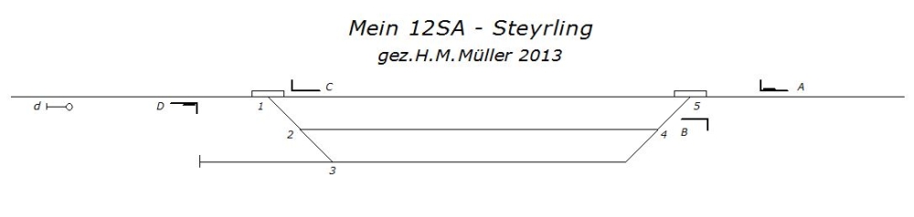
    Before we take a look at this chart, we need to know the track layout of the station—it is, as far as I know, Steyrling on the Pyhrnbahn (the line from Linz to Selzthal). On the right side of my lever frame, there is no lever for a distant signal, so I have to assume this signal was missing—although I actually cannot believe this: After all, this is and was always a main route, which would have been equipped with signals for running more than 40kph. However, as the lever for A only moves by 90° (up or down, depending on the number of arms), it is also impossible to connect a distant signal to the same lever (as would have been possible with German "Einheitssignale")—the friction in the long wire line would have been too large. The last possibility that comes to mind is a colour light distant signal that is controlled by arm contacts on A:


    At sporenplan.nl, the track layout of Steyrling can be seen in this track plan.

    And here is the locking chart for my lever frame (click on it to view it as readable PDF):

    My Austrian type 12SA lever frame

    Here it is: My own lever frame! It's type is called 12SA – this is an old Austrian type which was installed mainly at the end of the 19th century. I got my frame from club 760 in Mauterndorf, for a donation of a few thousand Schillinge. Most probably the interlocking was installed in Steyrling on the Pyhrnbahn, where it did duty up to the 1970s.

    Here is a first image, which shows all levers in their normal position (clicking on the image shows a larger version):


    Another start

    I might now start to translate a few texts of my blog in German to this site. The idea is that people around the world who are interested in mechanical machines, and especially railway interlockings, get something to see which they might not have seen or even known about up to now.

    In order to keep my workload down, I will mostly write much shorter texts than in my German blog, but keep all the pictures. If someone is interested in more detail, she or he can drop me a line—then I might expand the text of the respective posting.

    The types of interlockings used in Central and Eastern Europe have been quite different from those designed in  English-speaking countries. The main reason for this is that a few seminal inventions of Siemens (especially the Siemens block instrument), even though known and described in English engineering works, never found favour in England, ostensibly because they needed three line wires per bit of information; but also because of radical differences in the responsibilities of signalmen, linemen etc.

    This "interlocking divide" can been seen up to this time when one looks into wikipedia articles describing interlockings or details thereof—almost no mention is made of the respective "other side". When I find time, I might change this (and look how the various specialsts react). For the moment, I will just describe in English the devices that I have photographed in the 1970s and 1980s in Austria and its neighborhood.

    Still, the first few postings will contain recent photographs of
    • my own interlocking frame(yes, I do own one!)
    • a few very old interlocking frames in Germany.
    Only after these texts, the documentation of Austrian interlockings will begin.