Deutsche Version dieses Postings
Update 15.5.2016: Also this posting now contains comments and corrections by Hanspeter Thöni. His text contributions are shown in italic.
From
Brig, we took a train to Lausanne and then on to Biel, more or less just looking out of the window. A few snapshots were taken, but nothing memorable:
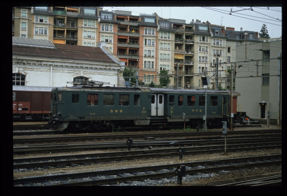
SBB Be4/4? 1615, where?, 16.8.1988
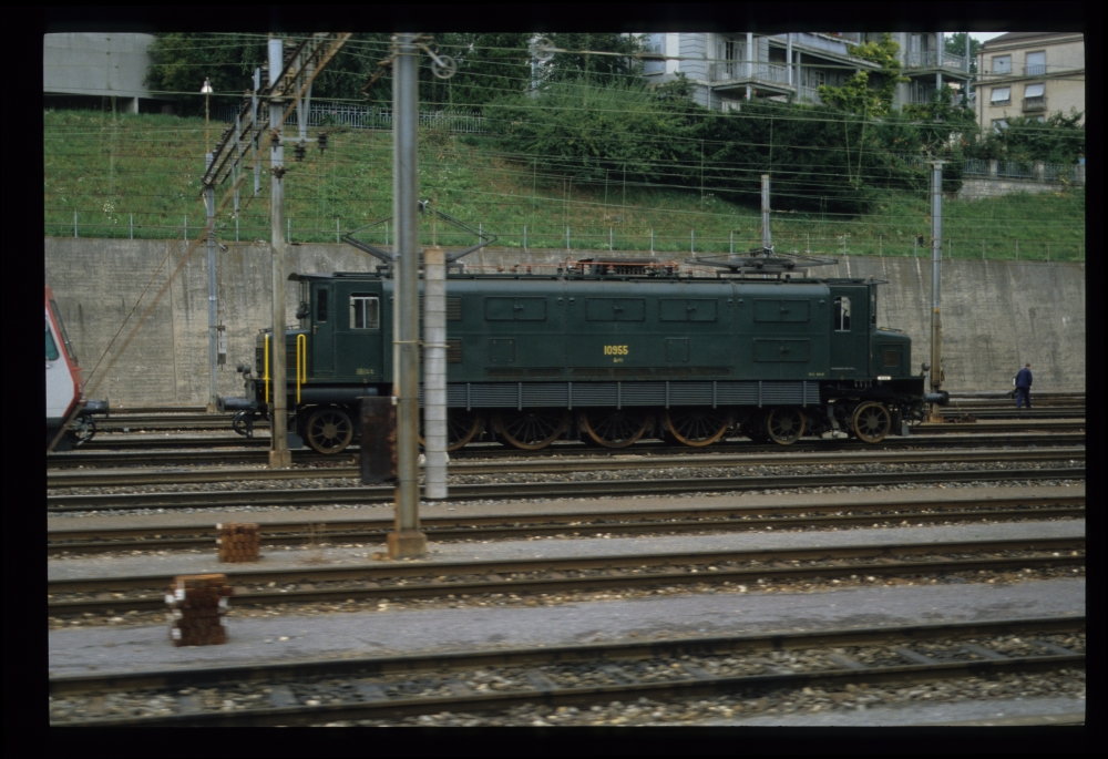
SBB Ae4/7 10955, where?, 16.8.1988
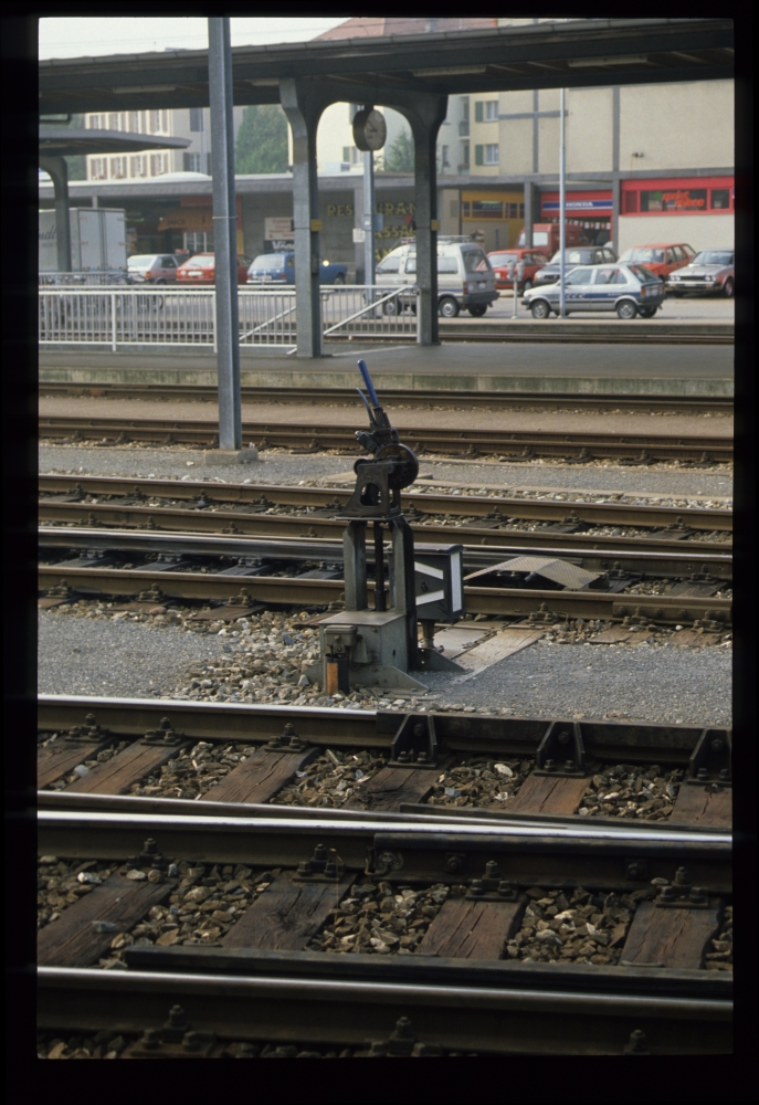
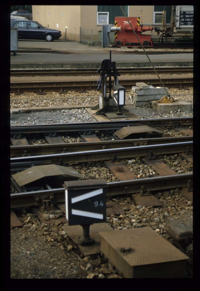
The next picture shows the minimalist "single lever ground frames" the Swiss use for many ground-operated points. Whether they did this for reasons of efficiency or safety, I do not know—probably a bit of each.
Hanspeter Thöni comments: These 'single ground frames' have another advantage: It is possible to see whether points were run through, as a seal would be broken in that case:
Points lever, Biel/Bienne, 16.8.1988
Points, Biel/Bienne, 16.8.1988
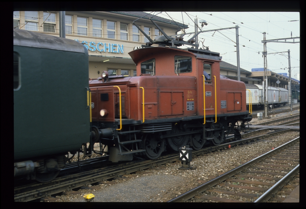
SBB Ee 3/3 16400, Biel/Bienne, 16.8.1988
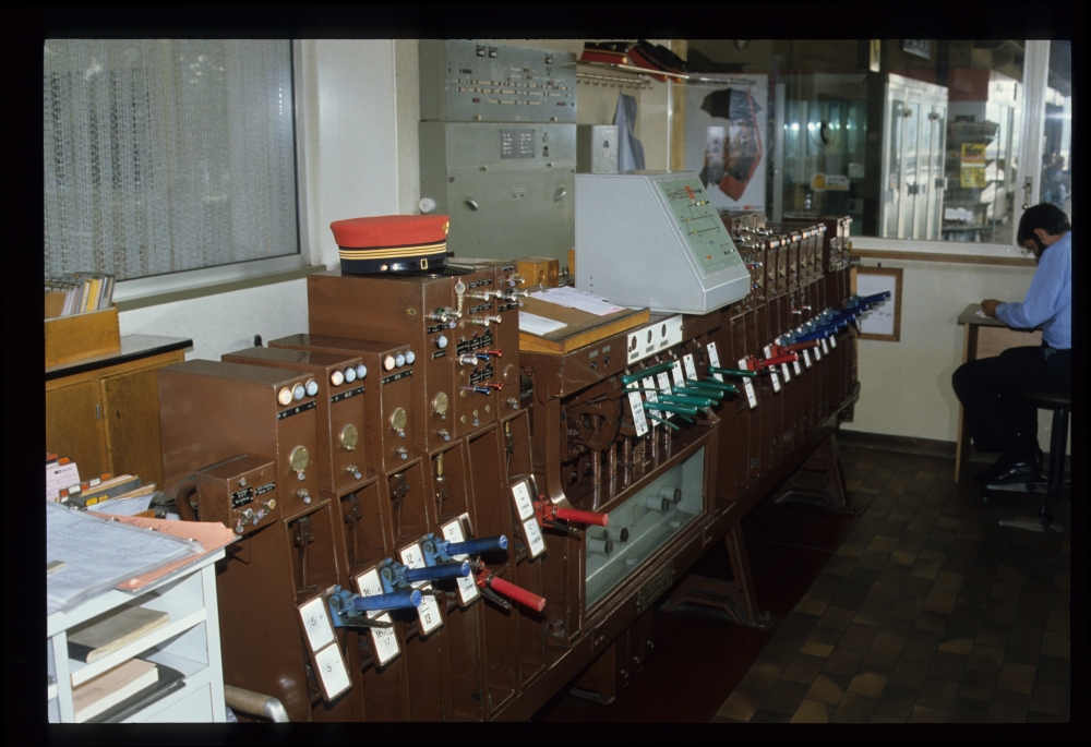
At Grenchen Süd, I took photos of the lever frame. It was an electromechanical frame, but built from parts of a purely mechanical one. Points and signals were controlled by levers originally designed as route levers, painted in blue and red. Additionally, traditional green route levers were also provided.
Using levers formerly used for route locking as points levers was done on various lines, e.g. throughout the line Luzern-Olten. The levers moved the locking bars as well as contacts in the lever lock above the lever:
Lever frame, Grenchen Süd, 16.8.1988
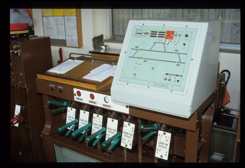
Here is a picture showing only the route levers—I will study them more below to show some Swiss specialties. Above the levers, there are three windows showing red or white for each main or loop track. I believe they only provide a mechanical feedback whether a route is set for one of these tracks, but I do not know their operation in detail.
The red and white discs are part of the 'virtual track occupation indicator' ('fiktive Gleisbelegung'). This is a mechanism from the times when not all tracks were provided with track circuits. A route into could only be locked when a white disc was shown in the window. When the route lever was reversed, a red disc was shown. This disc remained visible until the route lever for a route exiting the track was returned
to normal. The mechanism also enforces the following sequence of route locking: First, a route leading into the track must be locked, and only afterwards is it possible to lock an exiting route. In Switzerland, so-called 'simplified route order' ('vereinfachte Fahrstrassenreihenfolge') was used: An exiting route can be locked at any time, even if no entry route has 'virtually occupied' the track. In order to virtually occupy or clear a track—e.g. for a shunting move—, it was necessary to lock a 'blind route,' i.e., reverse and then return the route lever without clearing a signal.
On top of the frame, there is a small Integra panel for a level crossing in a neighbouring station, most probably Bettlach: For Grenchen Süd, neither the track numbers nor the layout nor the signal names do match, and Lengnau is larger. But why was the level crossing not controlled by Bettlach's train director—there must have been one there, because block working to Bettlach was still manual, as we will see below. Something is at odds here ...
Bettlach was provided with 'through-routing' (see the next posting from St.Blaise for a more detailed explanation). Thus, that station was at times not manned. It was customary for such stations that a Domino panel with a few functions (like barriers, emergency stop) was located in a neighbouring station. At Bauma in the Töss valley, such a situation has survived until 2014. For all other operations, the station had to be manned for local operation. The "line clear" indication that allowed trains to run towards a neighbouring station was only provided for single-track operations [e.g., in case of works]. When both tracks are available, no "line clear" request and indication are possible and needed.
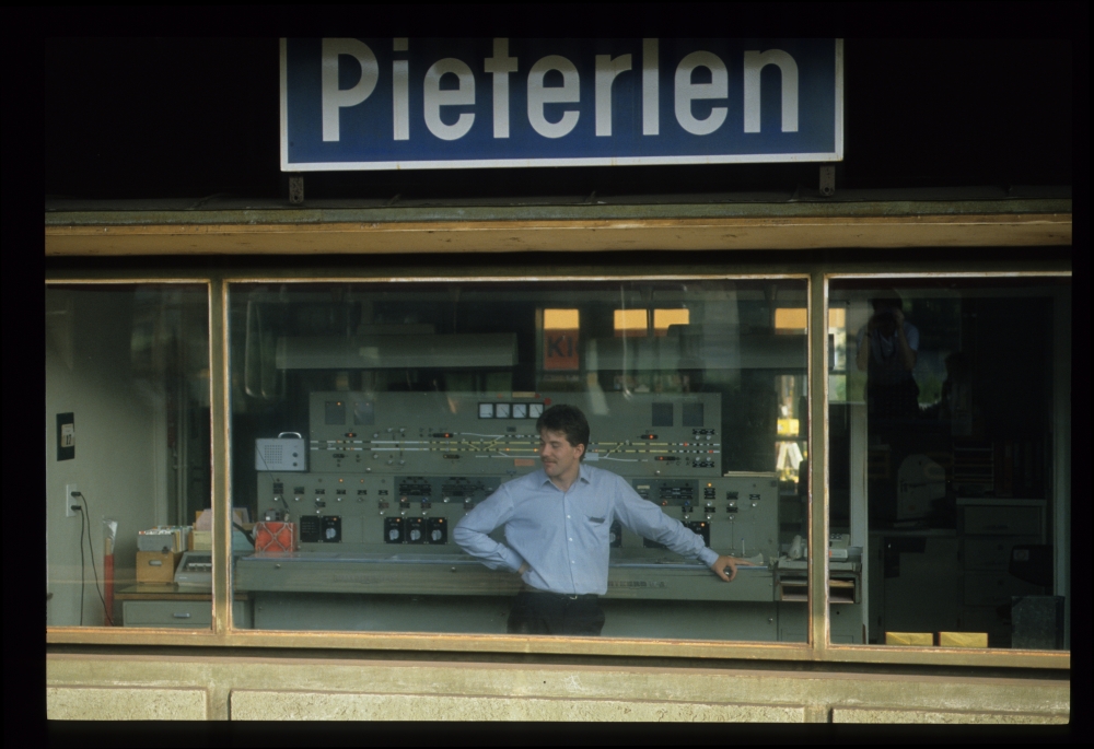
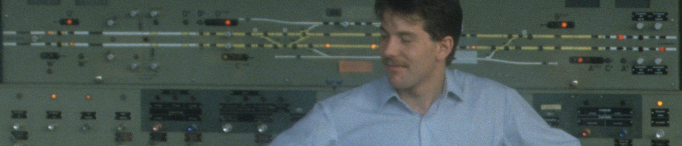
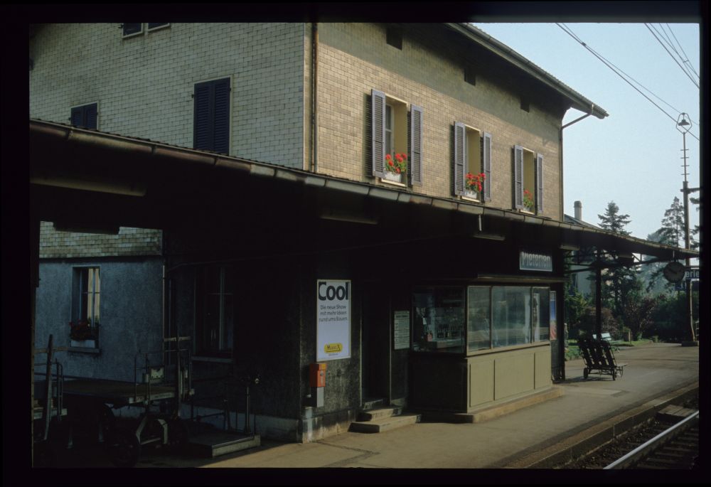
The picture of Pieterlen in the next posting shows that the block was not automatic. There were no track circuits or axle counters to check track occupation (which should have been clear, because there is clearly a button for acknowledging the arrival of a train). Therefore, the interlocking at Bettlach was certainly not provided with 'automatic through-running' (including automatic clearing of signals), but only with 'cut out' of that station from the line block, as no one could have signalled back "line clear" when the station was not manned.
In the bottom right corner, the panel contained a few more buttons for dimming the signal lights during night operation and for switching on and off the lighting in the points indicators here in Grenchen Süd:
Route levers and Integra panel, Grenchen Süd, 16.8.1988
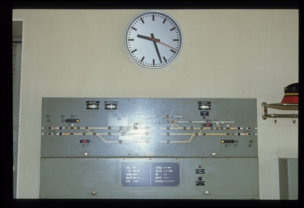
Here is a picture of the signal panel—unfortunately, my flash left a white spot in the center. Both home signals are cleared, but not the starting signals: This is somewhat puzzling, as for through trains (even when stopping at Grenchen Süd), the starting signals would typically have been cleared together with the home signals:
Track and signal panel, Grenchen Süd, 16.8.1988
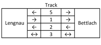
Here is my reconstruction of the track layout (
click opens a readable PDF file):
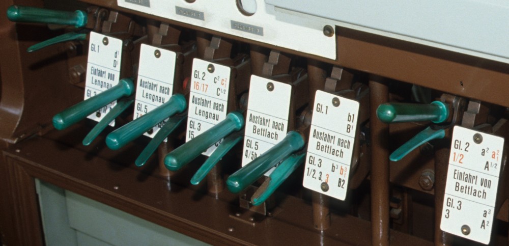
The following detail shows the route levers and their tags, which I'll use to construct a locking table:
Lever frame, Grenchen Süd, 16.8.1988
And here is a short table of the possible routes, which shows two special Swiss features. The routes going into and out of the main tracks 1 and 2 are obvious. Also the routes for track 3 are to be expected: This loop track can be used in both directions of travel. However, the routes out of track 5 would not be found in other Central European countries: After all, track 5 is the track at the goods shed, a typical shunting track. Yet, in Switzerland, it was customary that trains could directly leave such tracks towards the main line. Another Swiss feature is that one of this routes includes a derail.
This derail was necessary as there was no other flank protection from track 4 to track 1:
Here is my attempt to reconstruct the route table of this frame from the tags near the route levers. The italic plus signs have been added by me, as the route tags only show the points that have to be reversed.
In addition to the black marks, there are also routes and point numbers written in
red. Looking at the track layout and the block apparatus, I am quite certain that they indicate routes going to the right main track, instead of the standard left one. The reason for these additional routes was that on both sides of Grenchen Süd,
bi-directional single-track operation in case of works etc. had been provided. The red numbers are those of points that must be reversed for these opposing routes. For some routes (e.g.
b3f), these might be fewer than for the corresponding standard route, for others (e.g.
c2f), there might be more.
The line is not "banalised," i.e. provided for bi-directional operations. This would have required home signals on both tracks on each side.
When the interlocking frame was built, only routes from the left track into the station were provided. Running against signals on the wrong track was not possible. With standard two-track operations, it is also not possible with the enhanced frame shown here. However, when direct-current block working was introduced, the interlocking was provided with the possibility to take one track out of operation and use the remaining track as a single-track line. But this created a problem: It was now necessary to provide routes to and from this track when it was not the standard track in two-track operation. One possibility chosen quite often was to equip the frame with additional route levers. However, here, another method was used: Some route levers could lock two different routes in the same position, e.g. a2 and a2f. a2 is the route from signal A to track 2, whereas a2f is the route from signal A to track 2 from the wrong (German: falsch) track. A similar case can be seen with exiting routes b3 and b3f. The red colour indicates the route as well as the points needed for such routes.
However, I do not know the meaning of the red colour for points number
8, which can be seen on the route tags as well as near the corresponding points lever.
Florian Listl has suggested, and Hanspeter confirmed, that this means that the normal position of points no. 8 are into the diverging track.
Last, it is interesting to note the signal names: The small indices do not correspond to track numbers, but rather to the numbers of "arms cleared," even though the signals are of the colour light type. If two routes (a "black" one and a "
red" one) shared the same route lever position—e.g. c
2 and
c2f—, both indices were shown, e.g. C
1/2. The selection of the correct signal indication was obviously done by some circuits testing which points were reversed (
click opens a readable PDF file):
In addition to electric circuits, the points were actually also mechanically locked for the "wrong track routes": Special locking pieces, at times together with holes in the locking bars, provided the additional locking possibilities. In such cases, the correct position of the track could only be checked via electric contacts, but the lever could be mechanically locked in either position.
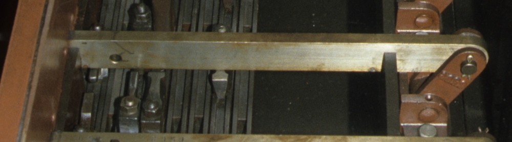
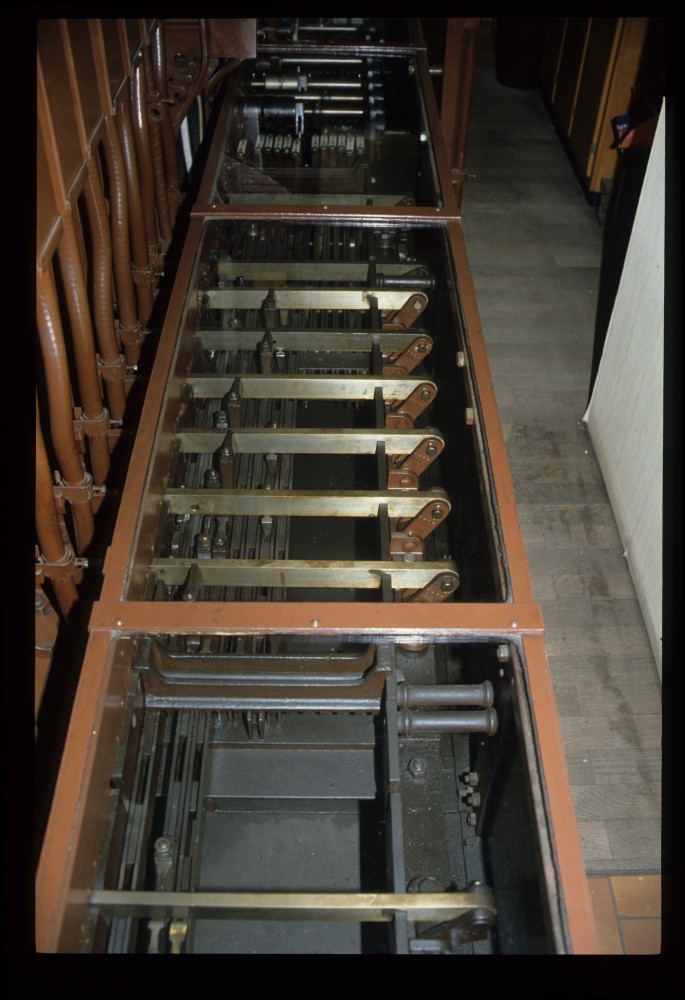
Such a hole can actually be seen in the picture of the locking bars below:
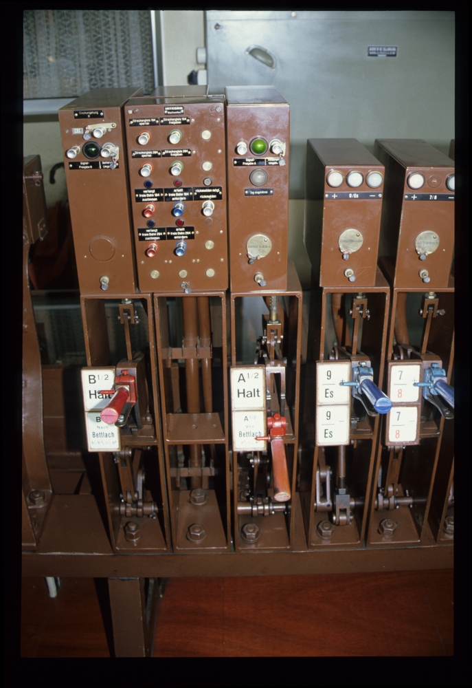
Here are the levers for starting and home signals on the Bettlach side and two points levers. The home signal A is cleared. The left points lever is for points 9 and derail Es (German for "Entgleisungsschuh", literally "derailing shoe"), the right one is for points 7 and 8:
Lever frame, Grenchen Süd, 16.8.1988
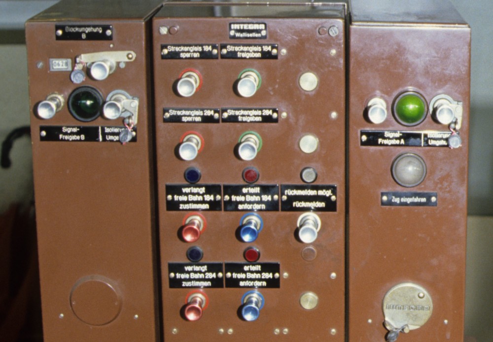
The presence of bi-directional operation can also be seen on this enlargement of the block apparatus: For both line tracks 184 and 284, it is possible to separately request "line free" ("freie Bahn") as well as signal "train permitted" ("Zustimmung") to Bettlach. A similar apparatus is provided for the tracks 186 and 286 to Lengnau.
Actually, request and permit was not given per train in this installation, but a general permit was given for one direction to run an arbitrary number of trains. Requests and permits per train were only given in the so-called OH block, colloquially called "Chrüzliblock":
Block apparatus, Grenchen Süd, 16.8.1988
The following pictures shows that this type of frame, designed by the German company Jüdel, was the direct predecessor of the German lever frame type "Einheit": All the main parts, from the locking and route bars to the route levers to the overall layout, everything is very similar to that German frame type:
Locking bed, lever frame, Grenchen Süd, 16.8.1988
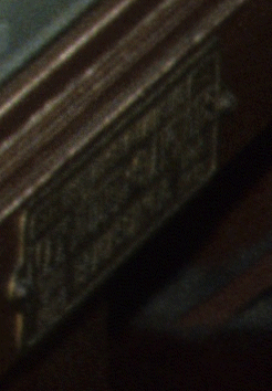
But I do not know who built this frame initially—it could have been Jüdel, but also a Swiss company like Hasler that had licensed the type. Here is an attempt to enlarge the builder's plate from the first image above—one could be tempted to decipher the name Jüdel in the middle.
The interlocking has definitely been built by Jüdel. If the old levers would have been present, that would be even clearer:
Last, here is a picture of the station building, with points 13 and 12 in the foreground:
Station building, Grenchen Süd, 16.8.1988