My photos from Mariestad are limited to the "centralapparat", a small type of electromechanical interlocking which used mechanical locking only to prevent setting up conflicting routes. Here is the frame:
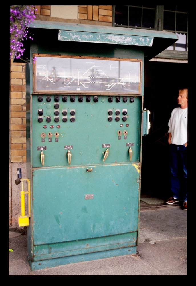
Interlocking, Mariestad, 17.7.1989
The following closeup of the panel shows a few details, some of which I do not understand:
- Not all points are moved by electric points machines—only the ones that are used for train routes in both positions. In Mariestad, these were (on the western side) points 2/17 (splitting the routes to tracks VI and VII) and points 8 (to tracks V and VI).
- The points' positions are indicated via small round lamps. The lighted bars near them are most probably the track circuits of the points.
- Even though no train route is set up, barriers V1 seem to be closed: Lamp N ("ned", i.e. "low[ered]") is lighted, whereas at all other barriers the U indicator is on ("upp", i.e. "up").
- Lidköping had two starting signals (sort of an inner and an outer starter). Here, on the other hand, we have two home signals: C is the outer one, D the inner one, which presumably protects the points into the station's tracks.
- Near starter E, there are two dwarf signal symbols stacked above each other and marked E as well. Why are two of them needed, and how are (or is) the dwarf signal(s) reversed?
- A loading spur with ground-operated points locked by keys is drawn at the upper left corner and connected to the main track with an arrow. However, it is not really clear (at least for me) where this track is located.
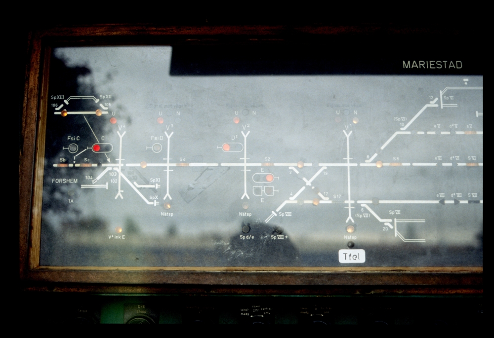
Interlocking, Mariestad, 17.7.1989
The following picture, taken somewhat later, shows a locked route into track 6 (route d2 VI, "Från Lugnås till spår VI"): The route lever at the lower left is turned, but there is no key inserted that would clear a signal (if I understand it correctly, the train director must be near the interlocking while a train signal is cleared):

Interlocking, Mariestad, 17.7.1989
This detail from the previous image shows various indicators (click opens it in full resolution):
- In track 6, a small arrow pointing to the right indicates the locked route d2 VI;
- at points 4/19 and 10, there are additional lights indicating that the points are locked in the route (why is this necessary for points 10?—maybe all points that are traversed by any train route are always locked together ...);
- the (lower?) dwarf signal E shows a red light:
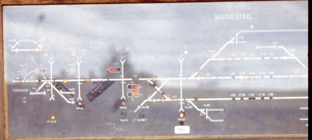
Interlocking, Mariestad, 17.7.1989
Here are the various switches and buttons for the left half of the station (again, click opens the image in full resolution):
- The topmost row contains two emergency stops, one for signal C, the other for both D and E. The next switch activates local control of barriers V1 ("Lokalmanövrering" = "local control"). To its right, there are two switches for activating local control of points 2/17 and 8 ("Växel" = "points", "lokalmedgivande" = "local permit", "centralomläggning" = "central reversal"). The next switch permits the local reversal of a number of points and derails for various spurs ("Medgivande 4/19/SpVIII, 6/SpVII, SpI, 3/SpII, 5/SpIII").
- The second row contains only a single button for raising barriers V1 ("V1 Upp").
- The third row contains a switch to permit local control of the (farthest) barriers V4, then a stop switch for barriers V1 ("V1 Stopp"), and finally two buttons for moving points 2/17 and 8 to the normal position.
- The fourth row contains three buttons for lowering barriers V3, V2, and V1 ("Ned" = "down") and tow buttons for moving points 2/17 and 8 into the reversed position:

Interlocking, Mariestad, 17.7.1989
And here are the controls at the bottom:
- The bottommost controls are the route levers. For the incoming routes to tracks V, VI and VII, there are separate positions "Från Lugnås till spår ..." = "From Lugnås into track ...", whereas there is only one common position for all three outgoing routes ("till Lugnås från spåren V VI VII").
- Above the route levers, there are the locks for clearing the signals (it seems that stop signals are always cleared with keys of type K15).
- The round indicators above them seem to be mechanically moved by the keys.
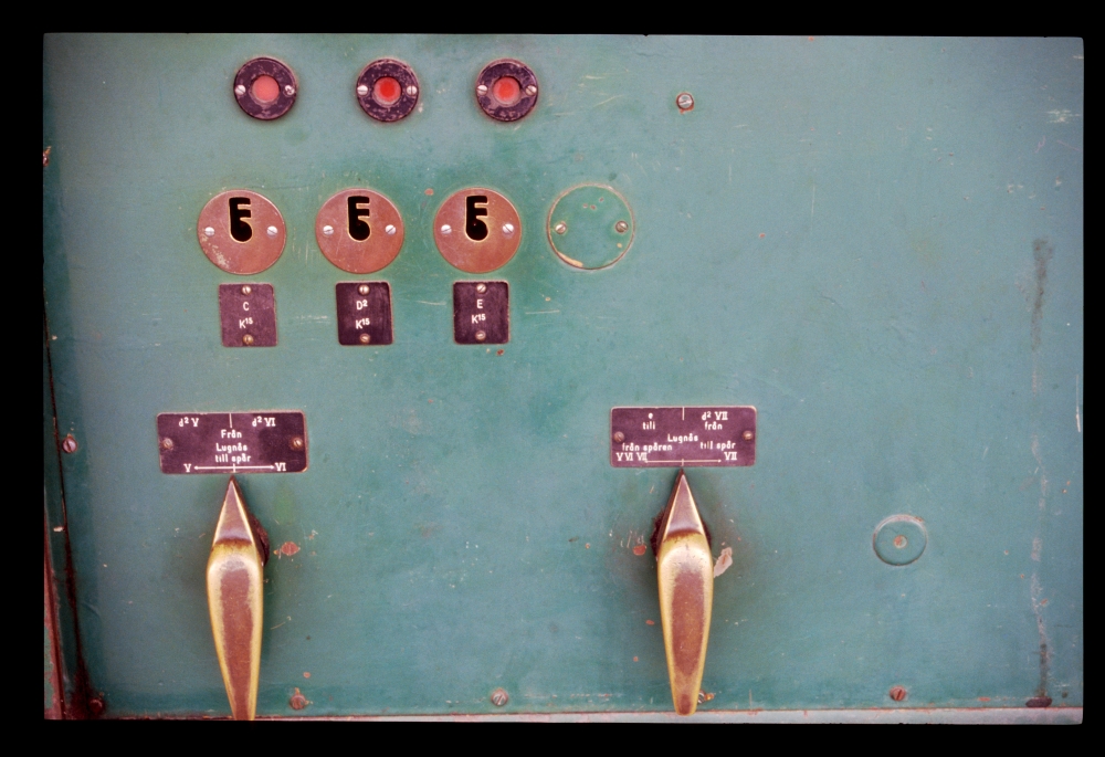
Interlocking, Mariestad, 17.7.1989
The following pictures show two sets of points. At ground-operated points 10, one can see the (most probably electro-magnetic) blade lock for locking the blades for train routes. On the points lever, there is a lock which releases the key for derail VI if the points are reversed.
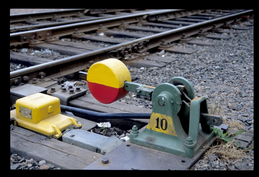
Points no. 10, Mariestad, 17.7.1989
This image shows the tips of the blades. The offset between the moving rod and the bolts in the blades, as well as the cover near the blade lock, indicate that the blades are pressed to the stock rails by blade locks. Nevertheless, the lever is mounted on two sleepers, and all parts are connected by heavy steel profiles:
Points no. 10, Mariestad, 17.7.1989
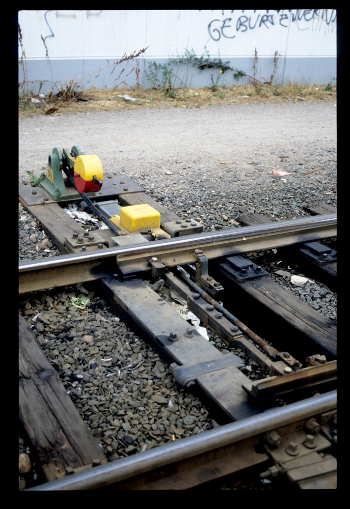
The next image shows a set of motor-driven points (probably no. 8, maybe no. 2). The point machine obviously uses inner blade locks, which requires a very stable connection to the stock rails so that a small distance between the closed blade and its stock rail can be guaranteed. Here, the heavy mounting is absolutely necessary:
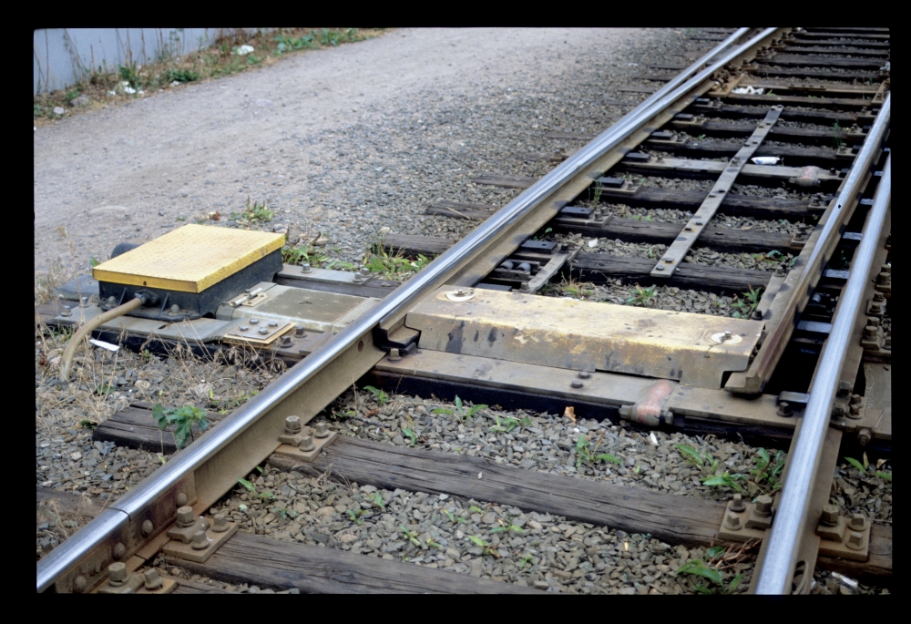
Motor-driven points, Mariestad, 17.7.1989
Finally, here is a picture of a small shunting engine. Behind it, one can see a corner of the great station building—there are a few photos of this grandiose building on the internet:
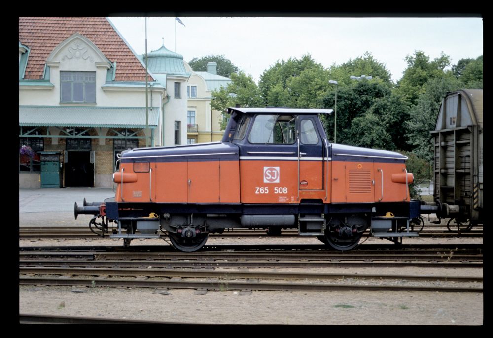
SJ Z65 508, Mariestad, 17.7.1989
No comments:
Post a Comment