My quite short remarks between the photos in my previous posting about Kreuzlingen were considerably expanded on by a long, explaining email from Hanspeter. This posting combines his text with details from my photos.
First, Hanspeter sent me a scan of the plan of the original, purely mechanical frame at Kreuzlingen. From that scan, I extracted the following drawing, which helps to understand some of the following items (Click opens an image with readable texts):
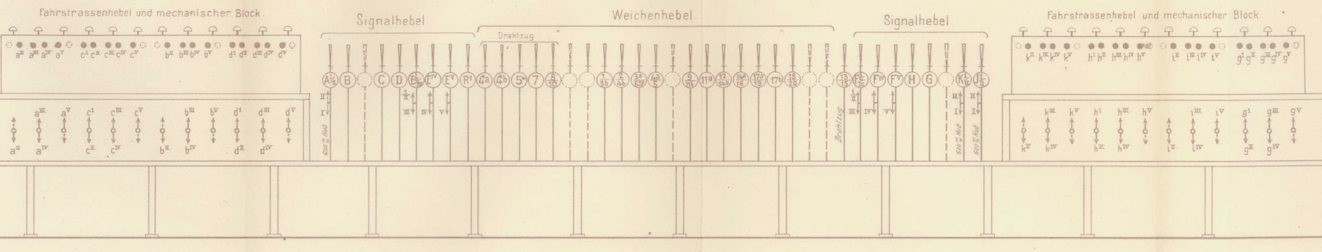
Plan of Kreuzlingen's old mechanical interlocking frame (Hanspeter Thöni)
The complete scan can be downloaded as a PDF from this link.
But here are, in italics, Hanspeter Thöni's explanations (translated by me, so any errors or misunderstandings are mine):
In 1988, the frames at Kreuzlingen were quite special.
The frame in the train bureau was not a standard command frame. Rather, the train director himself operated the train signals. For each line, there is a route and signal lever ("FSS"). I think that the train director could tilt the lever by 30°. This requested the route from the signal box. When the pointsman there had locked the route, the FSS was released to be reversed fully to the 90° position, which cleared the corresponding signal.
Line block working was also done by the train director. On the far left of the picture, one can see the sealed button 'Blockumgehung' ("block bypass"), additionally equipped with a counter.
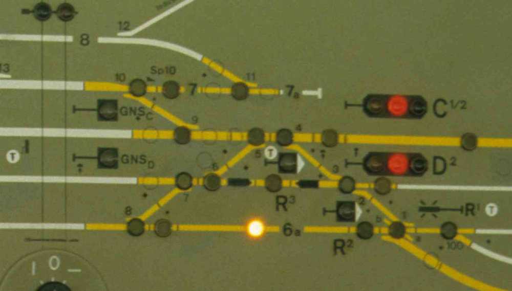
As one can see, there were no track circuits. Instead, Kreuzlingen used a sort of "virtual occupation indicators" (like the ones at Grenchen Süd); however, they used electrical circuits: In the track panel, each track had a red and a white lamp. One can see that at track 6, the "occupied" lamp is lit. In such a case, the FSS could not be moved past the 10° lock, so that a route could not be requested from the signal box. If one wanted to set up or clear such a "virtual occupation" (e.g. after shunting moves), one had to set up and immediately clear again a route request.
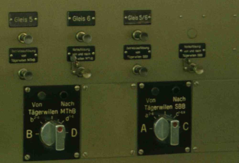
The barriers were also special. Two of the three were operated from the train bureau. One can see the corresponding switches in the track panel.
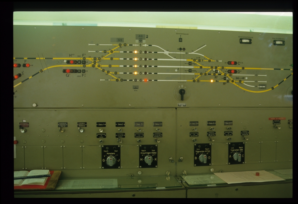
Track panel, train bureau, Kreuzlingen, 22.8.1988
It seems that the interlocking also allowed for one "deviation route" [my translation of the German "Umwegfahrstraße": An additional route from some track to another leading over different points]. This can be seen from the track selection button labelled "Gleis 5/6" ("track 5/6"). Most probably, the deviation route ran from track 6 via points 8/7 upwards and then down via the double slip switch to Tägerwilen MThB, and vice versa. In the short track (above 6a), there are two route arrows, and it is highly probable than one of them indicated the set-up deviation route.
Command frame, train bureau, Kreuzlingen, 22.8.1988
Command frame, train bureau, Kreuzlingen, 22.8.1988
The frame at the signal box also had its peculiarities: Both at the left and the right, there was a box for the route levers, whereas the points and signal levers were located in the middle. This arrangement was taken from the old, purely mechanical frame (see the plan above).
The following picture shows the left route lever box, and also the FPL levers a4 and b5,6:
Route levers, signal box, Kreuzlingen, 22.8.1988
The full labels of the levers contain the following text, as one can see (or guess) from the detail image:
- FPL lever a4 - Blade lock 5, 9
- FPL lever b5,6 - secondary lock ["Kontrollverriegelung"] 1a [I think]

FPL levers, signal box, Kreuzlingen, 22.8.1988
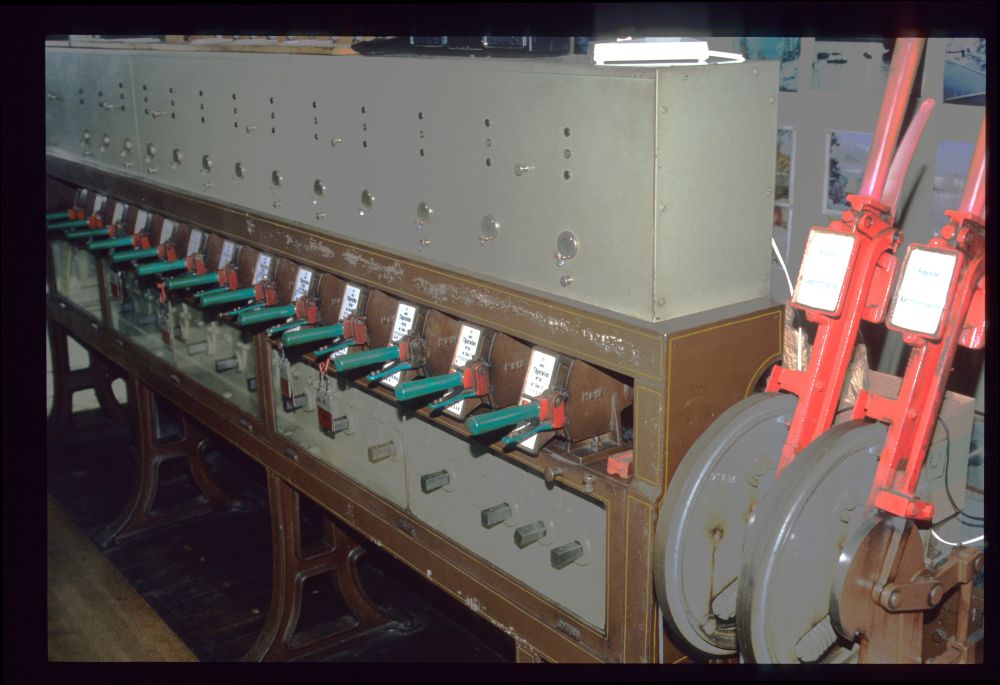
The following picture shows FPL levers k2,3 and i4. to their right is a route lever of the right route lever box, and to the left a switch for the single barrier that was not operated from the train bureau.
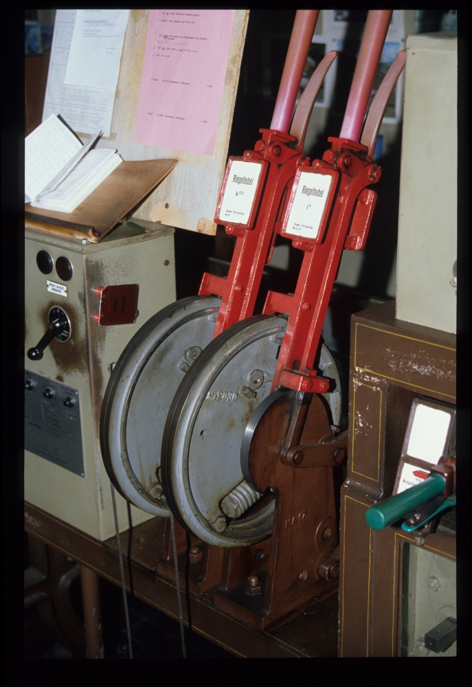
FPL levers, signal box, Kreuzlingen, 22.8.1988
Here is another detail of the labels of the two FPL levers:
- FPL levers k2,3 - blade-locks W 28
- FPL levers i4 - blade locks W 24, 27b

FPL levers-Detail, signal box, Kreuzlingen, 22.8.1988
About the four FPL levers: Looking at the old plan, one can see that the FPL levers are mounted exactly at the places of the former home signal levers, and they also had the same letters, only in lowercase. Well, these FPL levers actually moved the double-wire lines of the former home signals. But why? As one can read in my comments on St.Blaise, in former times the signal wires were used to lock facing points for routes over non-reversed points [this is standard practice in Anglosaxon interlockings, but quite special in Middle Europe, where route setup—including facing point locking—was always considered to be distinct from signal clearing]. This practice was also followed here. However, with the advent of colour light signals operated from the train bureau, the old signal levers were removed. But the points still had to be locked, and therefore, these FPL levers were put up instead, the double-wire lines were shortened to the farthest FPL, and the levers included in the route locking.
So much for Hanspeter's explanations, with many thanks!
No comments:
Post a Comment