On the 23rd of August 1988, I visited Zug (which, incidentally, means "train" in German—but here, it is just the name of a town in Switzerland) and shot the following pictures. Hanspeter Thöni, again, has provided a host of explanations and some corrections to my texts, which I intersperse here by marking them with italics.
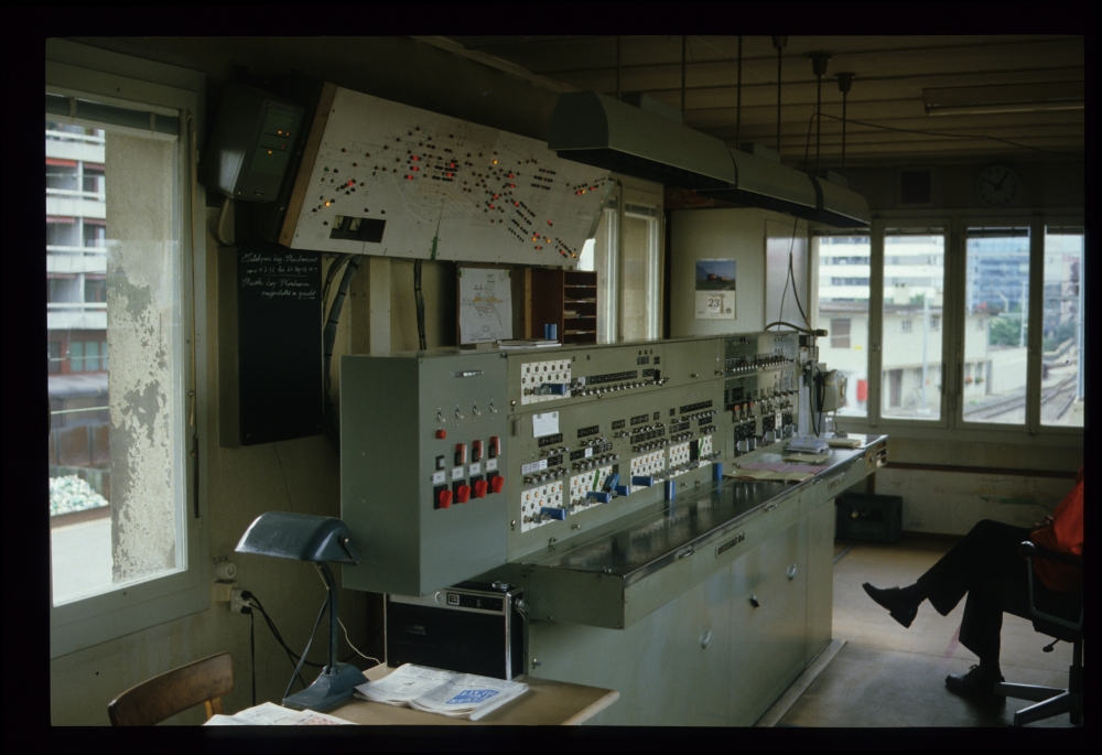
At Zug, the station was remodelled. The interlocking apparatus at signal box II had been modified with interim arrangements for the time being, as can be seen on multiple following images. Zug's track layout is like a wedge, i.e., the station building and the main platforms lie between the diverging lines to the Gotthard and Lucerne, respectively. As a consequence, the locations of the signal boxes were quite untypical:
- The main station building, at the tip of the wedge, contained the train bureau with an Integra command panel, which also controlled all the stations between Thalwil and Zug.
- On the eastern side of the point where the lines converged was signal box II, with an Integra frame.
- At the northern throat, near the junction to the "Zuger Schleife" (Zug loop), was signal box I, which also had an Integra frame.
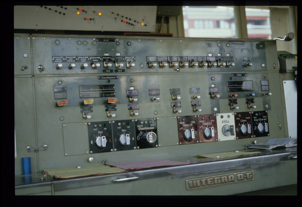
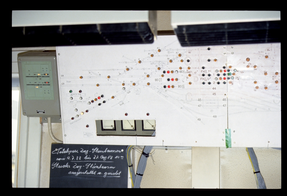
The following four pictures are from the train bureau. I made them towards the end of my visit, but showing them here makes explaining the station's signalling equipment easier. The first one shows the Integra panel used for the control of remote stations and as a command panel for signal box II. One can see
- in the uppermost row the line past the platform Oberrieden Dorf to the stations Horgen Oberdorf and Sihlbrugg (where the line to Sihlwald diverges),
- in the middle row Baar with the double-tracked line from Litti
- and at the bottom the schematic diagram of Zug itself, for command and line block working.
- Horgen Oberdorf and Sihlbrugg had [Integra] Domino 55 relay interlockings without shunting routes.
- Litti and Baar each had a Domino-67
- Zug had a command panel and Integra frames at the signal boxes
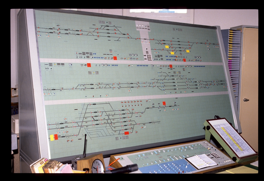
Integra panel, train bureau, Zug, 23.8.1988
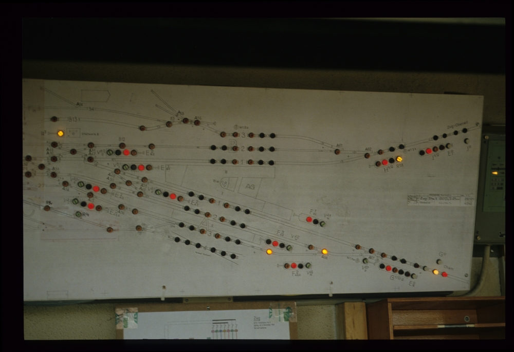
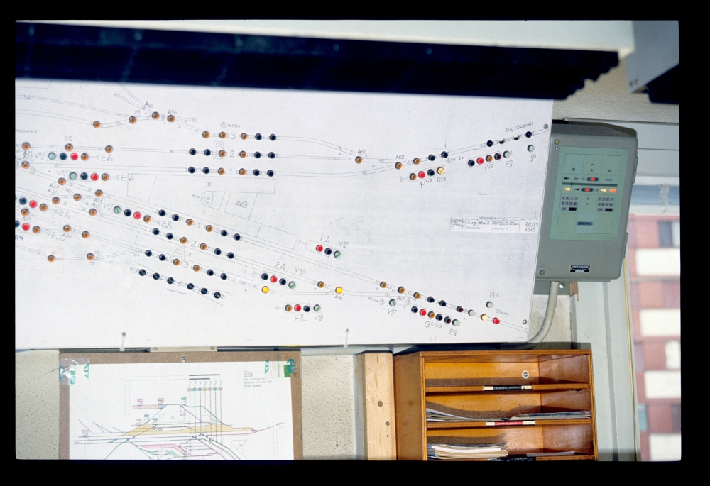
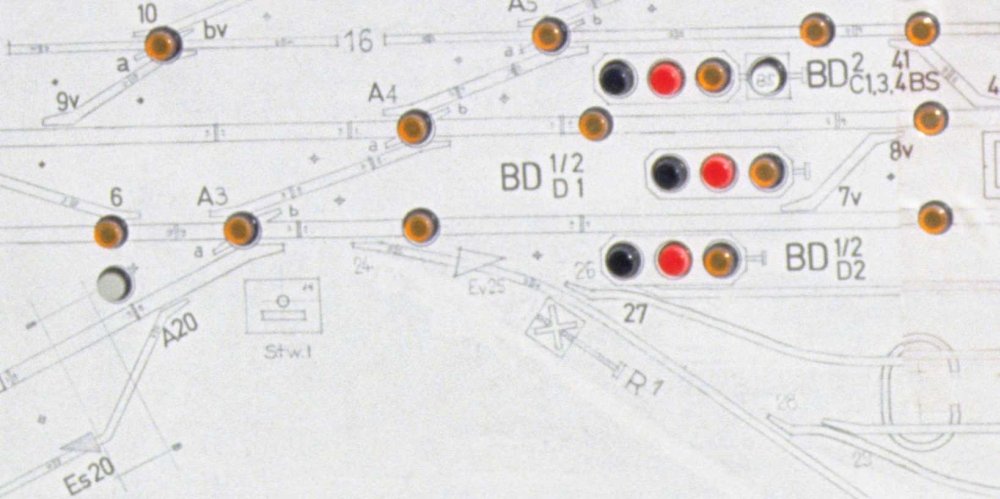
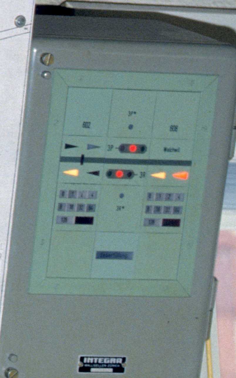
The next two pictures show the diagram for Zug itself, with a manually added connection between tracks D1 and C4:
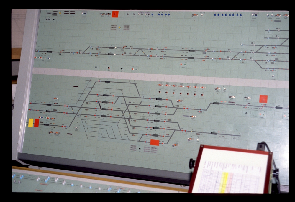
Integra panel, train bureau, Zug, 23.8.1988
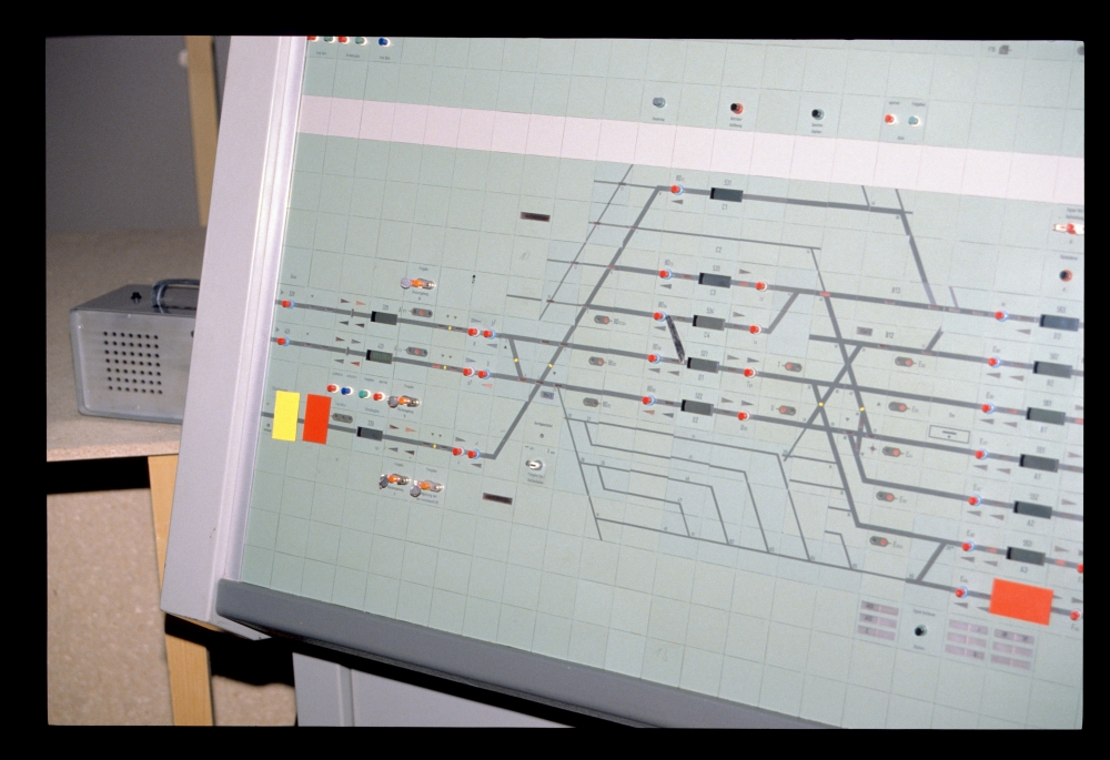
Integra panel, train bureau, Zug, 23.8.1988
On the fourth picture, one can see Sihlbrugg:
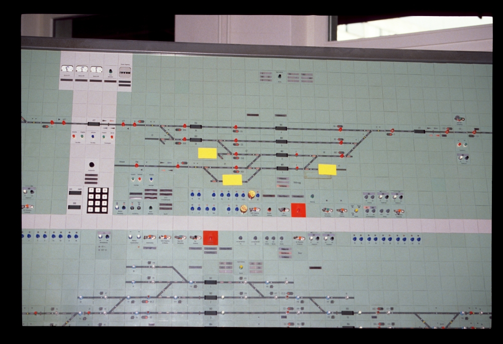
Integra panel, train bureau, Zug, 23.8.1988
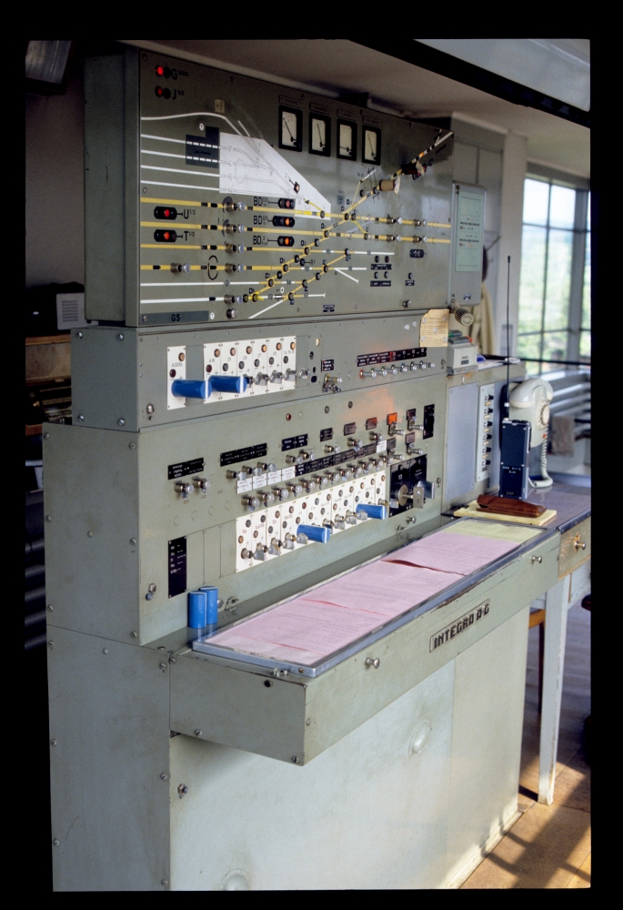
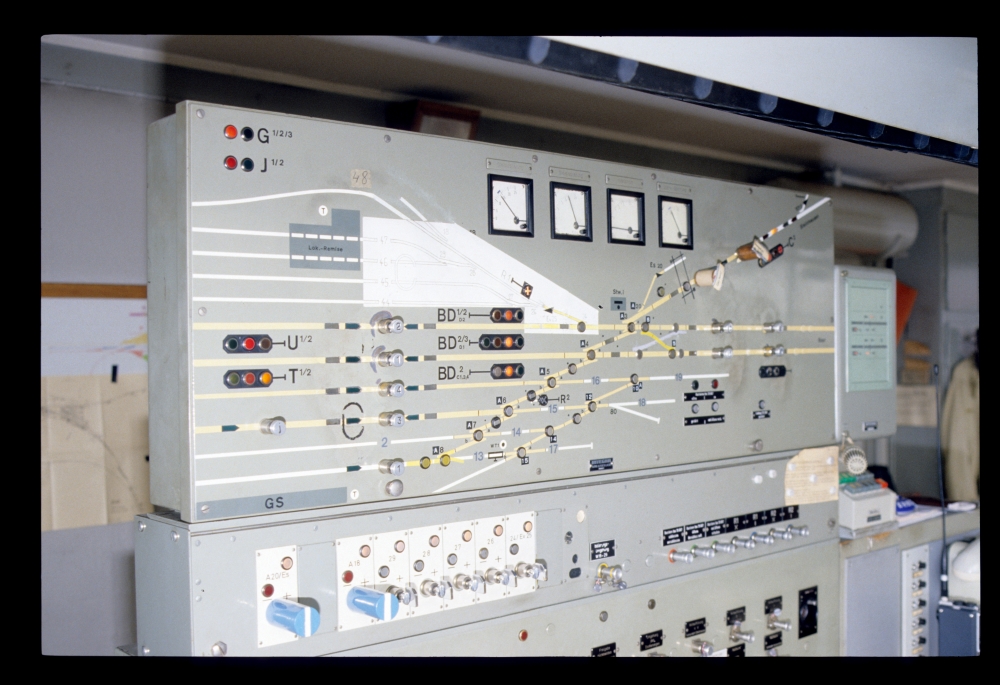
The train routes and signals at Zug were cleared from signal box II. Here is the interlocking apparatus:
Interlocking, signal box II, Zug, 23.8.1988
Four new (or recently electrified) points behind the locomotive shed were controlled from these switches.
These switches, which are quite untypical for railway use, could only be used because these points are only used for shunting moves. Thus, a simple "shunt points" circuit could be used, without a track circuit. Thus, they might be reversed when occupied. A simple lamp shows that the blades are in one or the other end position. Also, these points cannot be locked in a route. If a locomotive runs through the points, no alarm is sounded—the motor will simply start again and try to move the points to the end position. This also explains why there is only a single fuse for each set of points, which is for the motor circuit—a control circuit, and a second fuse for it, is absent.
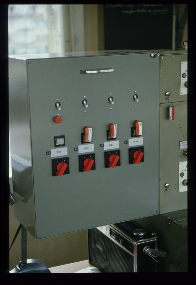
Points switches W61...W64, signal box II, Zug, 23.8.1988
Here is the left part of the panel:
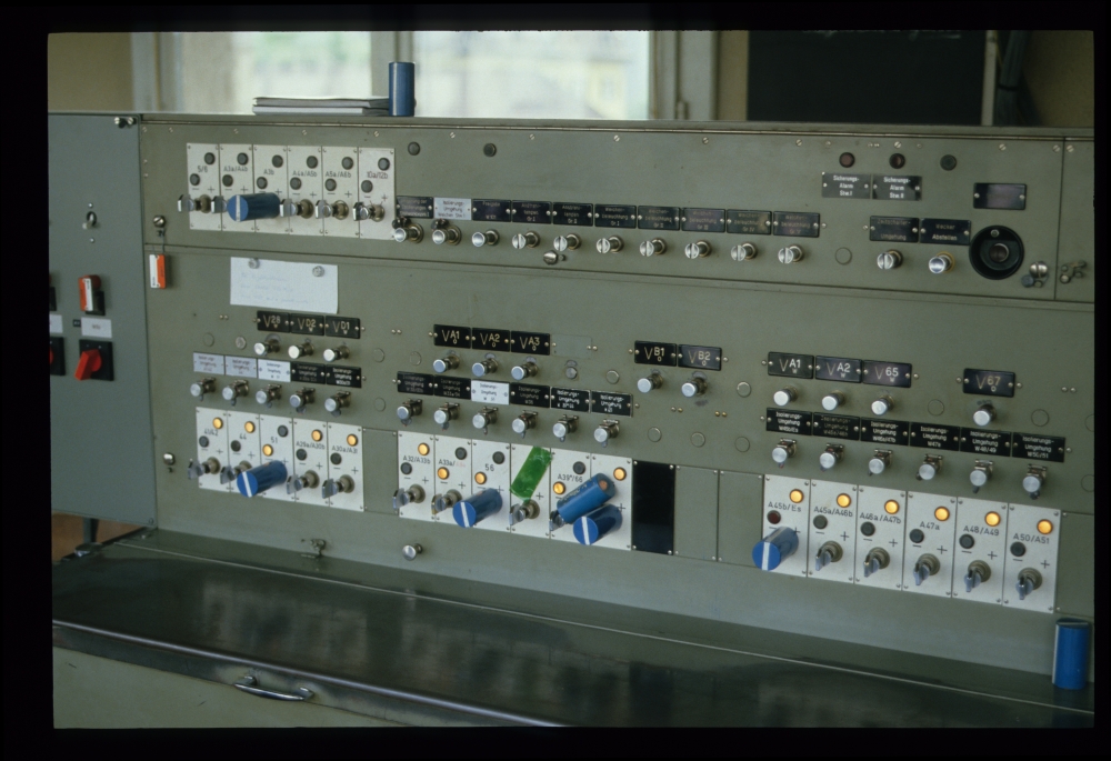
Panel, signal box II, Zug, 23.8.1988
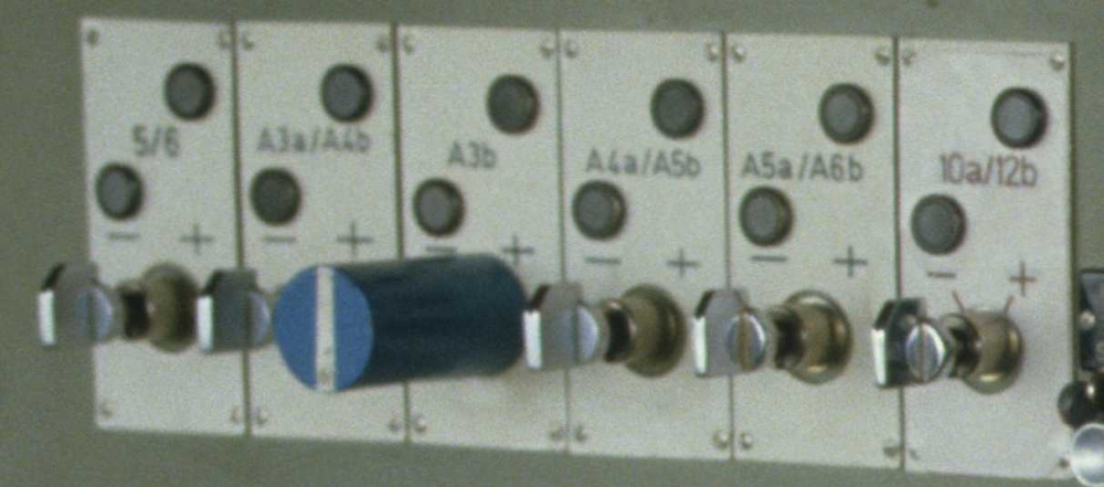
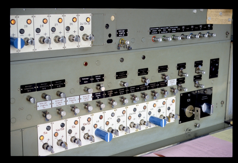
The following picture shows a few points switches, or rather, buttons.
The standard switches are, electrically, buttons. In this case, relay modules for points had been installed which allowed for points control via single pulses. The buttons were no longer mechanically locked. Also the older Integra frames did not have a locking bed, but the large points switches still had locking magnets that prevented the handle's movement when the points were locked in a route or occupied. The tilting buttons here, in contrast, could be turned at any time, but of course, when a set of points was locked or occupied, it would not move.
The much smaller tilting buttons for points had not only the advantage of using less space, but also allowed for the automatic route setup when the route-and-signal switch was turned. However, I do not know, whether this feature was present at Zug.
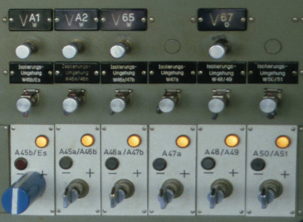
The switches shown on the following picture are exactly those which controlled points that could be controlled from both signal boxes. As signal box I was active at that time and hence controlled these points, the control lamps here are dark:
Points switches, signal box II, Zug, 23.8.1988
And here is a row of buttons for
- track circuit bypassing for signal box I,
- unlocking of points W101 (we'll see the key that is released later on a picture from signal box I),
- groups of lamps and, finally,
- groups of point indicator illuminations:
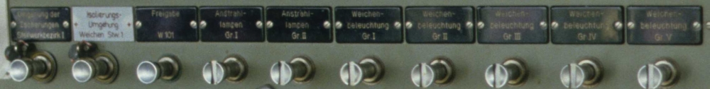
Buttons, signal box II, Zug, 23.8.1988
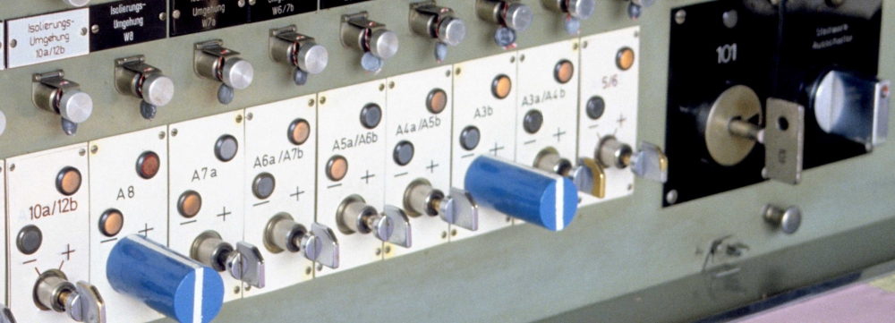
The following section shows:
- Buttons for shunting signals,
- more track circuit bypass buttons and, below them,
- points switches.
Buttons, signal box II, Zug, 23.8.1988
Here is the right part of the panel with switches for train routes.
The route switches are actually route-and-signal switches, which combine both functions (45° tilt for route locking, 90° for clearing the signal). Also here, one can see a host of special cases. The switches are marked with uppercase letters for the corresponding signals (or signal groups) B, A, D, C, F, G, H, J, as well as the inner signals U, T. The track plan, however, also contains a group of signals marked E (starting signals towards Baar or Steinhausen). However, there are no corresponding switches. What is going on here?
For an arriving train, one would first set up a route from one of the home signals A, A(f) or D to the inner signals T or U. On the track panel, one can see that on the line from Steinhausen, there is a distant signal TU* on the home signals. Thus, the home signal could be cleared, with the inner signals still at stop. From T or U, another route would then be set up to the platform tracks B1-2 or A1-4.
For departing trains, such a process was not possible. The reason is that the distance between the inner signals E... and the starting signals BD... was too short—thus, there were no distant signals mounted on the E... signals. Therefore, one could not set up a route from an E... signal to a BD... signal that would clear the E... signal (the train would not have been warned of the BD... signal showing stop). Still, the complete route was set up in two parts, by turning switches T and U to the left. They both have a label eD1 and eD2, which are the partial route from E... to track D1 or D2, i.e., up to the starting signals BD... Turning one of them to the 45° position would lock the partial route. However, signal E... would remain at stop. Now, one would clear the starting signal (switch B to Baar or D to Steinhausen). Any only after the starting signal BD... had cleared, also E... would show a proceed aspect.
With today's Domino-67 interlocking, it became possible to signal a train route from the inner signal to the starting signal. For this, the signals E... got the additional proceed aspect 6 (yellow over yellow = short route).
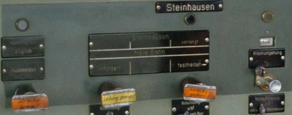
The following picture also shows some consequences of the remodelling. The dark grey grids commonly would contain the buttons for line blocking. In the lower row (Steinhausen and Cham), this is still so. But above, for Baar and Oberwil, that custom had been ditched: Buttons for barriers and other purposes were mounted into the existing grid wherever there was a free place. Moreover, some route switches' labels had not been corrected: There are still red marks for routes af and bf, even though such wrong-way routes did no longer exist with bidirectional running.
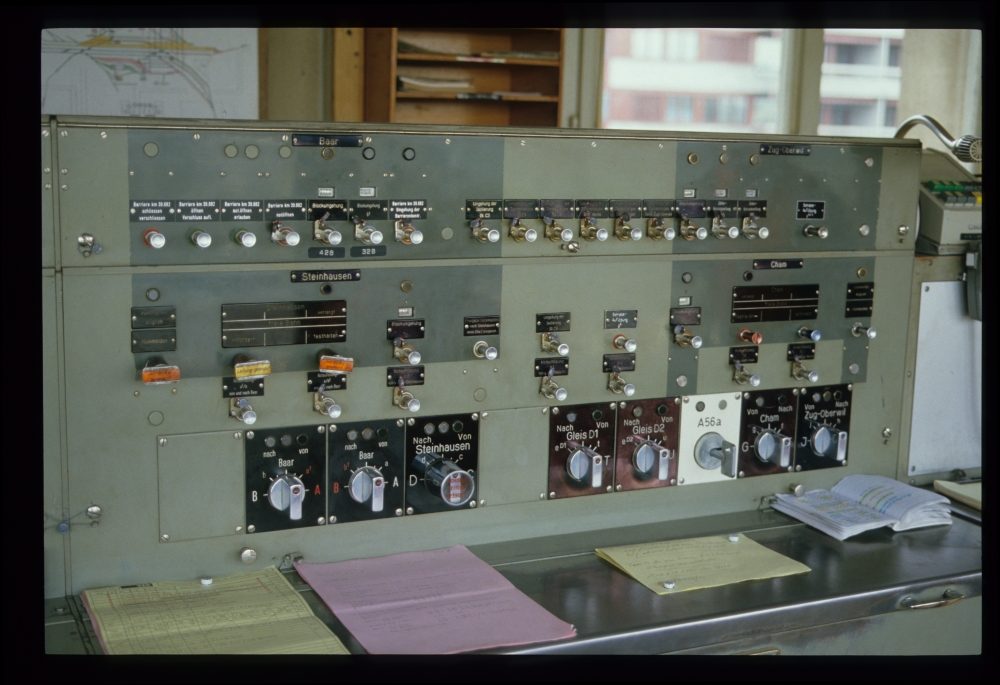
Integra frame, signal box II, Zug, 23.8.1988
The upper row contains a few buttons for a barrier.
This barrier control is of a newer generation. One can also see that the button labels are quite new. For trains, this barrier would not have to be closed separately. Just setting up the route would trigger the barrier's closing. And as long as the barrier was not fully closed, the signal would not clear. After
the train had released the route, the barrier would automatically open. For shunting moves, however, one had to close it with the button 'Barriere ... schliessen/verschliessen'. In this case, the barrier would not open automatically, but had to be opened with the button 'Barriere ... öffnen/Verschluss aufl.'. However, there is an additional button 'aut.öffnen erlauben' ("enable automatic opening"), which, when pressed, would cause the barrier to open after it was cleared by a the next movement. The same buttons were also present on signal box I, as the barrier had to be controlled by both signal boxes :
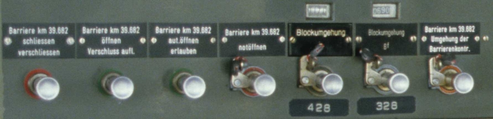
Barrier controls, signal box II, Zug, 23.8.1988
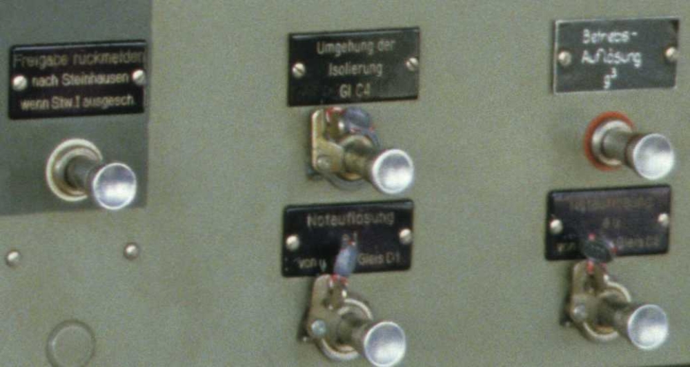
The leftmost button on the following picture shows that signal box I could be cut out—it says "Block back to Steinhausen when signal box I is switched off" ("Freigabe rückmelden nach Steinhausen wenn signal box I ausgesch.").
I am astonished about the button 'Betriebs-Auflösung g3' ("Route release g3"). In those years, route release had long been automated. The reason for an additional possibility to release that route can be seen when studying the track panel closely. The concerned route is g3, i.e., a train arriving from Cham on track 3. The track panel shows that there is a set of points in the middle of track A3, which would be travelled against facing points. However, automatic releasing would require that the points had been reached by the train (i.e. its track circuit would have to be occupied). But when a short train arrives, which would not pull up to the points? For this case, the signalman had the responsibility to release the route with this special button:
Signal box II, Zug, 23.8.1988
Here are the line block controls for the "Zug loop" (to Steinhausen). The line is closed, and the overhead line is grounded, as one can see from auxiliary locks over the lower buttons:
Signal box II, Zug, 23.8.1988
The next picture shows the route switches for arriving and leaving routes on the lines to Baar (Thalwil) and Steinhausen (Zug loop). Also here, there is an auxiliary lock over the switch towards Steinhausen because of the closed track:
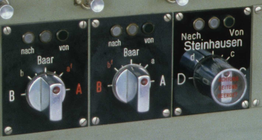
Signal box II, Zug, 23.8.1988
Here are the other route switches, also for inner signals T and U, as well as a key for one half of a slip switch moved on the ground:
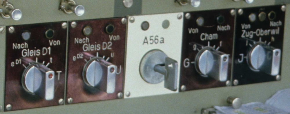
Signal box II, Zug, 23.8.1988
And this picture shows the complete apparatus:
Signal box II, Zug, 23.8.1988
An temporary track plan had been drawn on paper and then been glued to a wooden panel:
Signal box II, Zug, 23.8.1988
Signal box II, Zug, 23.8.1988
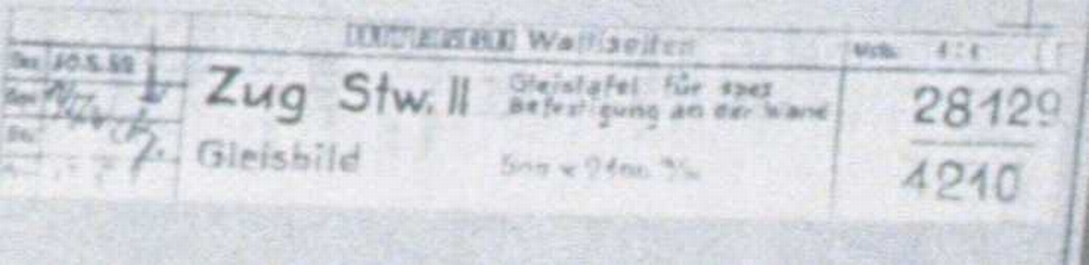
On the right, somewhat had written precisely: "Gleistafel für spez. Befestigung an der Wand", i.e. "track panel for special mounting to the wall", and, with a no longer correct abbreviation, "500 x 2100 m/m":
Signal box II, Zug, 23.8.1988
Here is the left side of the panel:
Signal box II, Zug, 23.8.1988
The following detail shows how the engineer had placed the symbols very precisely. Only the uppercase C of the track group on the lower right is a little confusing—the upper two lines do not really meet where they should:
Signal box II, Zug, 23.8.1988
The man who had made this cutouts for three gauges, on the other hand, had had a somewhat more tweedy approach. From the left to the right, these are gauges for the points current (Amperes), control voltage (36 V) and track circuit voltage (12 V):
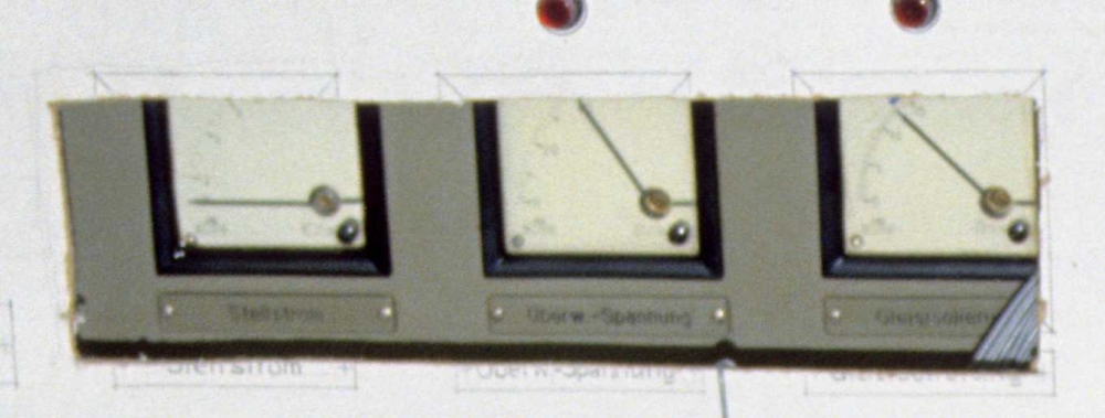
Signal box II, Zug, 23.8.1988
And below the track plan, this panel shows the exact duration of the line closure—four days after my visit, it would be reopened:
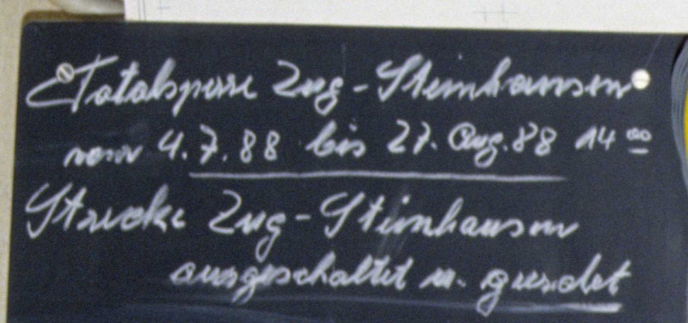
Signal box II, Zug, 23.8.1988
The line blocking equipment was quite different for the various lines. Towards Steinhausen and Cham, there were no track circuits or axle counters, and hence manual blocking back was used. Te line towards Baar was track circuited (as can bee seen from the light transparents in the additional Domino panel). And the line towards Oberwil had axle counters, with the peculiar binary display of the registered axles. There were nine lamps, indicating 0 (no) axles, and then 1, 2, 4, 8, 32, 64, and 128 axles counted in. This shows that trains of no more than 255 axles could be allowed on the line. And one had to sum up the numbers if one wanted to know exactly how many axles hat entered.
Signal box II, Zug, 23.8.1988
Signal box Iwas only for shunting moves. However, it had control over some points in train routes. But I do not know how these points were locked. It could be that some of the buttons in the track panel shown in one of the next images would close a self-keeping "points are locked" circuit for signal box II, which would be broken from there after the train move.
I agree that the buttons on the track panel at signal box I would lock the points and allow signal box II to set up routes over them. Maybe they also aligned the points correspondingly.
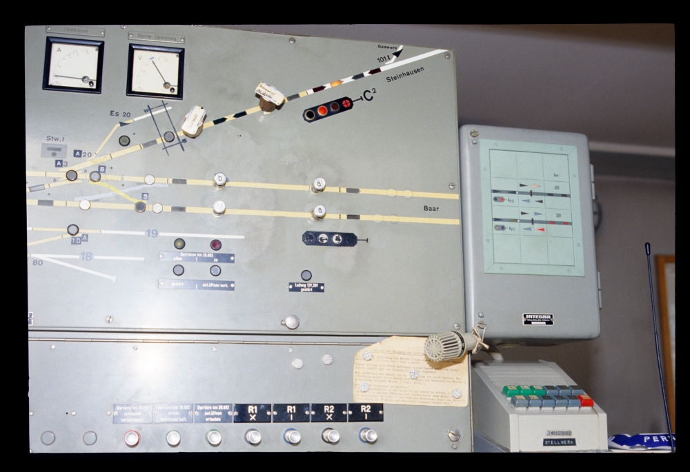
Here is the interlocking apparatus:
Signal box I, Zug, 23.8.1988
On top of the lower part, an additional part was added (maybe later) for more points switches and other buttons.
The track plan in signal box I shows that points W 101 were located in the line to Steinhausen. The key was in signal box I, as the line diverged there and the conductor for the move to the spur (formally not a train, but a "line shunt move") did not have to go to signal box II. But as block working for the line was done from signal box II, the key had to be locked and released from there. For such a move, it was necessary to have the line blocked (which happened via a telephone call with Steinhausen), and moreover the direction of the line block system had to be from Zug to Steinhausen.
Next to the key, there is the switch for cutting out the signal box, which resulted in some points being controlled from signal box II:
Signal box I, Zug, 23.8.1988
Here is a row of switches for exactly the points whose control can be handed over to signal box II:
Signal box I, Zug, 23.8.1988
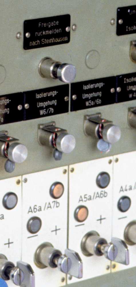
Somewhere above, the button 'Freigabe rückmelden nach Steinhausen wenn Stellwerk I ausgesch.' ("Block back to Steinhausen when signal box I is switched off" at signal box II was mentioned. This lead me to search the photos for the corresponding button in signal box I. One can see it on the previous image, and somewhat enlarged below, in the middle above the points switches. As has been mentioned, line block working was done at signal box II. Signal box I, however, was exactly the box at the lines' ends. Hence, the pointsman at box I had to check the completeness of an arriving train and then send that information it to box II, who would then block back. With signal box I cut out, the signalman at box II could do this "to himself". Whether he always could see the trains' ends, or whether he had to walk outside, I do not know, however ...
Signal box I, Zug, 23.8.1988
The following is an image of the right side of the track panel.
One can see nicely that the line to Baar had directional running in earlier times: There is the old, single, no longer active home signal symbol and four covered arrows of the former block system. For the new indicators for signals and block working, a small Domino panel had been added:
Signal box I, Zug, 23.8.1988
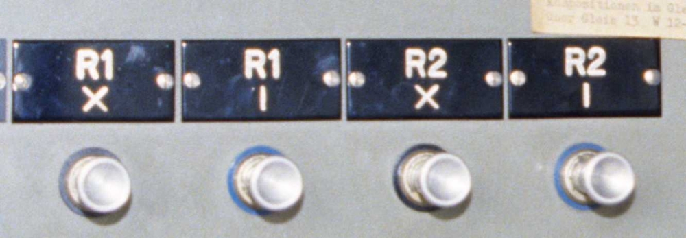
The two clearing signals R1 and R2 were controlled with these four buttons. This is the same type of signal as R1 at Kreuzlingen, only as a light signal, not a mechanical one:
Signal box I, Zug, 23.8.1988
Here is, once more, the track panel and the uppermost rows of switches and buttons:
Signal box I, Zug, 23.8.1988
On the right side, some magnets held an instruction sheet:
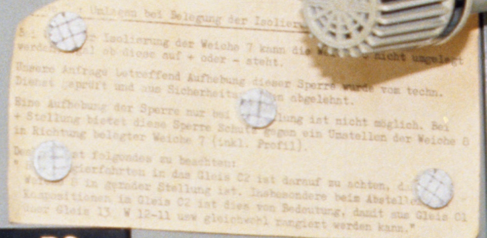
Signal box I, Zug, 23.8.1988
Here is it text, as far as I can reconstruct it—I have added parts in brackets (and repaired it at one place after a suggestion of Hanspeter). An English translation follows below:
[?] Umlegen bei Belegung der Isolier[ung der Weiche 7]And here is the translation to English:
Bei [belegter] Isolierung der Weiche 7 kann die [Weiche 8] nicht umgelegt
werden, egal ob diese auf + oder – steht.
Unsere Anfrage betreffend Aufhebung dieser Sperre wurde vom techn.
Dienst geprüft und aus Sicherheits[gründe]n abgelehnt.
Eine Aufhebung der Sperre nur bei [- Stel]lung ist nicht möglich. Bei
+ Stellung bietet diese Sperre Schutz gegen ein Umstellen der Weiche 8
in Richtung belegter Weiche 7 (inkl. Profil).
Des[halb i]st folgendes zu beachten:
" B[ei Ran]gierfahrten in das Gleis C2 ist darauf zu achten, da[ss die]
Weiche 8 in gerader Stellung ist. Insbesondere beim Abstelle[n von]
Kompositionen im Gleis C2 ist dies von Bedeutung, damit aus Gleis C1
über Gleis 13 W12-11 usw gleichwohl rangiert werden kann."
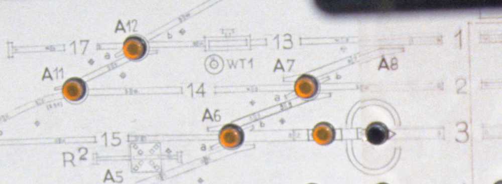
[?] Reversing when points 7 are occupiedHere is the relevant part of the track plan for this instruction from the track plan at signal box II:
If the track circuit of points 7 is occupied points 8 cannot be reversed, irrespective of whether it is in + or – position.
Our request to remove this lock was denied by the technical department for safety reasons.
Removing the lock only when the points are in – position is not possible. In + position, the lock prevents inadvertent reversing of points 8 towards points 7 including the necessary clearance.
Therefore, the following must be observed:
When shunting into track C2, points 8 must not be reversed. Especially, this must be observed when placing a composition in track C2, so that it is possible to shunt out of track C1 via track 13 and points 12–11."
Signal box II, Zug, 23.8.1988
Signal box I, at least, got a photo fom the outside. In the backgrund, the Zug loop curves towards Steinhausen:
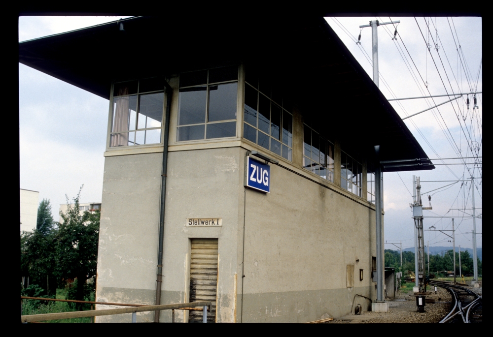
Signal box I, Zug, 23.8.1988
And I took this photo of two points indicators:
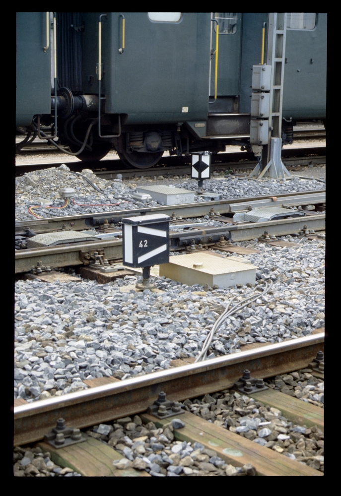
Points 42 and 52, Zug, 23.8.1988
The following signals are most probably also from Zug. I had taken the photo two days earlier on the platform:
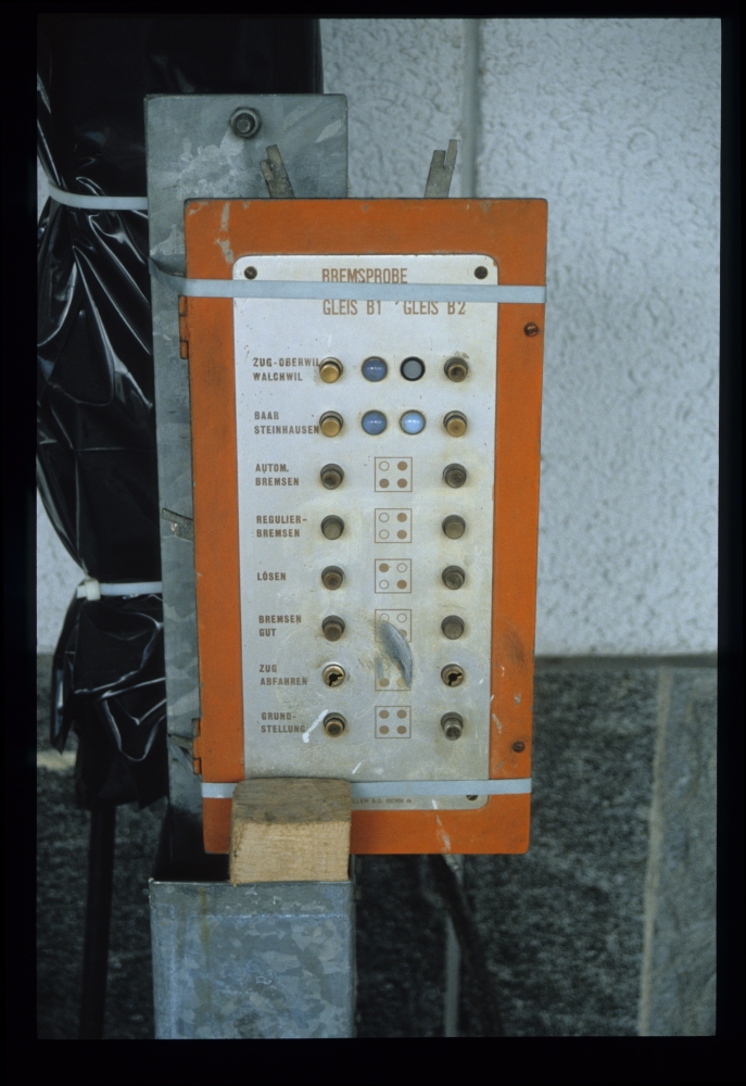
Panel for brake and "right away" signals, Zug, 21.8.1988
And that was all from the quite special and interesting interlocking systems at this important SBB station.
No comments:
Post a Comment